Turbo Charger Simulation Project
What is Turbocharger & where it is used?
As we know that in automotive applications we use a supercharger to boost the engine power but this reduces the engine efficiency by 20% in order to avoid this problem a turbocharger is used. A turbocharger is a device that supplies the more air by pressurizing intake air & thus increasing engine power output & this turbocharger is driven by exhaust gas. The turbocharger was first patented in 1915 by swiss engineer Alfred Bucchi.
A turbocharger is also used in Aircraft applications because as we know that pressure decrease as altitude increase & because of this lesser pressure aircraft couldn’t able to produce sufficient amount power in order to avoid a turbocharger is used.
Construction & Working of a turbocharger?
A turbocharger consists of three main components which are as follows:
- Turbine
- Compressor
- Housing
Turbine & Compressor are placed in separate chambers & they are connected by a common shaft. This shaft is supported by pair bearing & the bearing is lubricated by the engine oil. When it comes to location turbocharger is placed close to the engine exhaust manifold in order to avoid engine loss.
Working
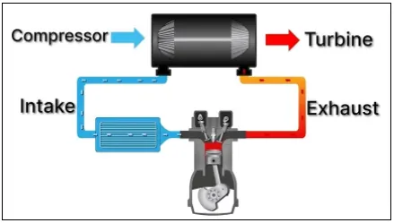
When the engine is running the hot gas from the combustion chamber leaves the exhaust manifold and expand this expansion of hot gas against the blades of the turbine makes it run so when the turbine & compressor run as they are connected with a common shaft then the compressor increases the pressure of air & thus more compress air is supplied in the intake manifold.
When the engine runs at the slower speed the flow of the exhaust will be also low & hence turbocharger will run at a slower speed which means there will be insufficient boost produce which is required by the engine this is the disadvantage of the turbocharger this means turbocharger is directly proportional to each other.
Advantage:
- The energy of exhaust gases of the engine which amounts to be ⅓ of energy supplied is put to work for economical gains.
- The exhaust of the engine becomes considerably quite.
- As exhaust gas gets considerably very less which means the engine will produce fewer emissions.
Disadvantage:
Turbo-lag:
- In the engine, there is the time lag between the increase in engine speed & the increase in turbine speed which is known as turbo lag.
- If the wheels of the turbine are small the turbo lag can be small but it will perform poor at the higher speed of the engine & if the wheels of the turbine are large it will perform well at higher speeds but there will be a lag at a lower speed so, in order to avoid & get an optimal performance both at high speeds & low-speed several modifications has done with the turbocharger which as follows:
- Twin turbocharger
- Twin scroll turbocharger
- Variable geometry turbocharger
Overboosting:
Sometimes the turbocharger overboost the engine which causes severe damage in the engine & to avoid this turbocharger use a wastegate which is as follows:
Wastegate
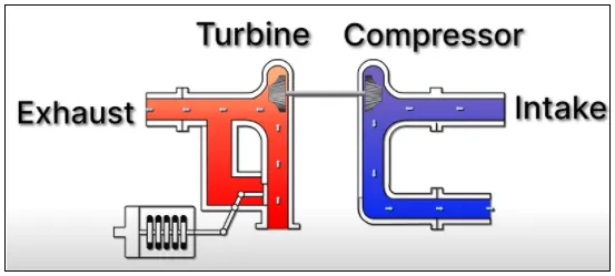
A wastegate is situated at the exhaust inlet of the turbine & it is operated by using a solenoid which is controlled by ECU.
When the wastegate valve is closed:
When the wastegate valve is open:
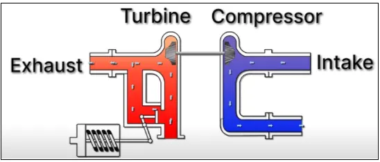
From the above images, when the solenoid valve is closed all the exhaust gas reaches the turbine but when there is an excessive boost the solenoid valve opens & which in turn makes exhaust gas bypass the turbine & flow directly to exhaust.
Intercooling:
The turbocharger uses an intercooler to cool down the inlet air before it reaches the engine.
Objective:-
To Simulate the fluid flow through the Turbocharger in order to find the impeller speed for the following 3 different pressure ratios :
- Pressure ratio = 2
- Pressure ratio = 2.5
- Pressure ratio = 3
Geometry:
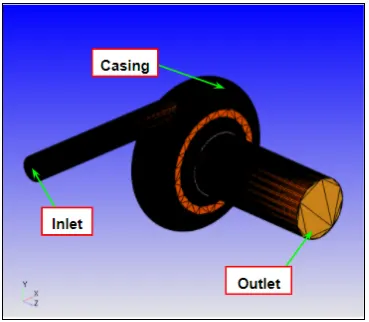
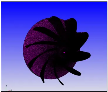
The pre-modeled geometry was imported into Converge and the geometry was inspected for surface error or other errors. After fixing all the errors & the boundaries were flagged & case was set up.
Turbocharger
Turbine:
Case Setup:
- Application: General Flow
- Solver: Transient solver
- Simulation Type: Gas
- Material: Air
- Simulation mode: Full hydrodynamic
Simulation time parameters:
- Start time:0 sec
- End time:0.006 sec
Region & Initialization:
In this step, we have created a region of the fluid and initialize the species value as follows:
- N2=0.77
- O2=0.23
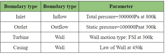
Boundary Conditions:
All the boundary conditions are defined at temperature=300K.
Physical Model
Turbulence model:k_e-epsilon
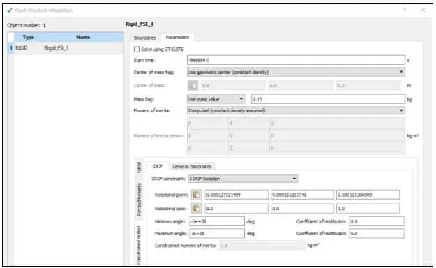
Fluid-structure intersecting modeling:
The interaction between the fluids & the solids is the phenomenon that can be seen in nature, for example, the deformation of trees caused by wind.
In almost the same manner the exhaust gas interacts with the turbine & exerted the pressure force on the turbine that can lead to deformations. These deformations can be quite large or very small, depending on the pressure and velocity of the exhaust gas and the material properties of the turbine. In order to simulate such flows, a Fluid-structure interaction modeling is used which is the subset of multiphase modeling.
Grid Control:
- Element size:dx = 4e-3m, dy = 4e-3m & dz = 4e-3m
Output Files:
- The time interval for writing 3D output data files: 6e-05 sec (So, that we get at least 100 3D output files)
- The time interval for writing text output:1e-5 sec(So, that we get every minute )
- The time interval for writing restarting output:6e-05sec
- Maximum number of restart file saved:3
Post-Processing
Mesh
Total cell count
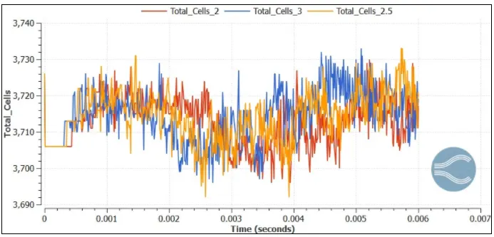
From the above, we can see that the total count changes as the turbine rotate also we can see that the total cell count plot is the same for all 3 different pressure ratios.
Mass Flow Rate
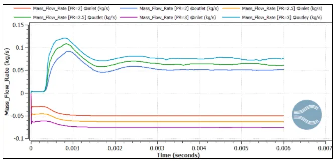
From the above plots, we can see that mass flow at the inlet is equal to the mass flow rate at the outlet so we can say that mass is conserved also we can see that mass flow is converged
Torque
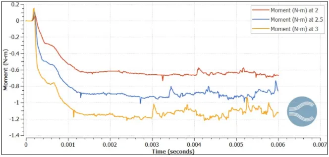
From the above plot, we can see that as pressure ratio increases torque acting on the turbine is also increased and also we say that torque is almost converged.
Rotational velocity
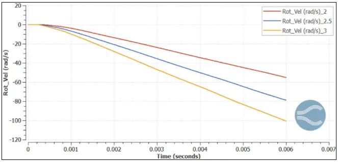
This is an interesting plot as we can see the rotational velocity of the turbine is goes on the increase continuously which means the turbine still its accelerating phase & it’s not converged also we can say that as pressure ratio increases the rotational velocity is also increases.
By looking at the above plot the convergence can be defined in two ways.
If your concerned how mass flow rate occurs at inlet & outlet or how much torque is acting on the turbine then running the case till 0.006 sec is enough but if we want that turbine should attend its maximum speed then we need to run the case from a number of seconds
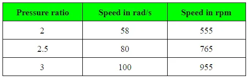
Speed of the impeller
With the help of the above plot, we can tabulate the speed of the impeller for 0.006 sec time for different pressure ratio:
Pressure Contour:
The pressure acting on the Turbine
From the above contour, we can say that turbine is evenly loaded as one side of the impeller where the jet is impinging on the surface of the turbine the pressure is maximum this type of loading is also called asymmetric loading also we can see that flow separation is occurring at the backside of the impeller.
Velocity contour:
From the above the contour, initially, the impeller doesn't start to rotate because of its inertia but when the torque acting on impeller goes above its threshold the impeller starts to rotate.
Conclusion:
- Turbocharger simulation was done successfully.
- Study of asymmetric loading & flow separation which is acting on the turbine done successfully