Super Charger Simulation Project
Introduction: We all know that the engine develops power by burning an air-fuel mixture & hence to increase the power output the more fuel has to be combusted in each cycle of engine operation & since the engine burns the specific air-fuel ratio more air has to be added when you want to add more fuel. At a normal operating condition, the air supplied in the engine during the intake stroke is at atmospheric pressure as the pressure of the intake air increases the density increases which means more air will be inducted in the engine thus more air & more fuel will result in greater combustion & greater power this can been achieved by a supercharger
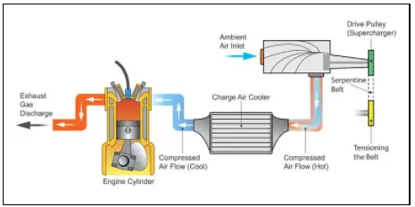
Supercharger: A supercharger is a device that supplies more air inside the engine cylinder by pressuring it & thus produce greater combustion & greater power. The supercharger is a mechanical device that is driven by the engine by means of a belt or gear. As the supercharger is connected to the engine it can respond immediately without delay based on the method by which air supplied by the supercharger can be classified into two main types which as follows:
- Positive displacement supercharger
- Dynamic compressor supercharger
Positive displacement supercharger: This type of supercharger supplies an equal amount of air at all conditions here the volume of air which is supplied by the supercharger will be constant at all engine speed this type of supercharger can be further classified into two types:
- Roots-type
- Twin Screw type
Dynamic compressor supercharger: This type of supercharger supplies more air into the cylinder by accelerating the air to a greater speed the most commonly used dynamic compressor supercharger is the centrifugal supercharger.
Advantage:
- Power required is the less for the given pressure ratio
- Initial cost & maintenance cost is low
- It increases the power output of an engine without increasing fuel consumption.
Disadvantage:
- Knocking: As all supercharger supplies the intake air at high pressure so as the pressure increases the temperature will increase as the temperature increase inside in the engine cylinder may ignite the mixture spontaneously even before the initiation of spark this results in uneven combustion or knocking so to avoid this supercharger used an intercooler which is used to cooling the air before it enters the engine cylinder.
- Engine efficiency drops: As superchargers rely on the engine for functioning they draw power from it and this will reduce the engine efficiency so in order to avoid these a turbocharger is used.
Objective:-
To Simulate the fluid flow through the Supercharger in order to find the mass flow rate for the following four different pressure ratios :
- Pressure ratio = 1.1
- Pressure ratio = 1.5
- Pressure ratio =2
- Pressure ratio =2.2
Geometry:
The pre-modeled geometry of the supercharger is imported into Converge and when the geometry is inspected for error we get many of the errors which as shown below:
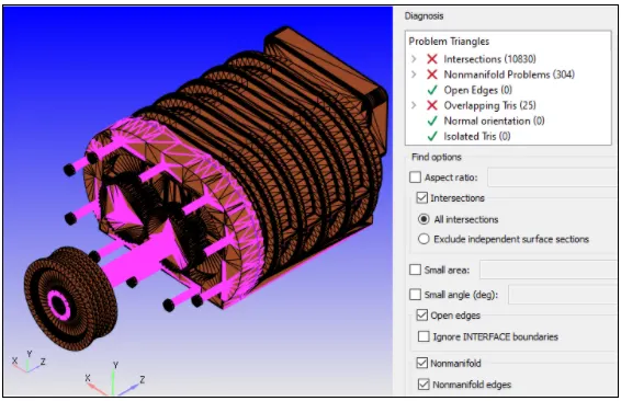
In order to run the simulation successfully, we first need to get rid of these errors which we have done in the following steps
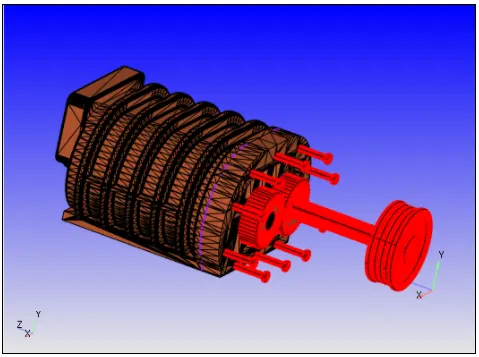
Since we are doing flow simulation so which means we are not concerned with the parts which are not contacted with the fluid so we can just directly delete them as shown in the above image.
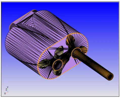
By deleting the solid part we get the fluid volume which is shown in the above image.
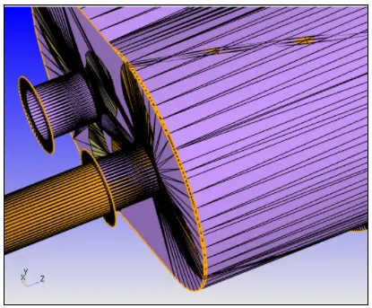
From the above image, we can see that the lobes are intersecting to the casing, to get rid of this we will first delete the face of the casing and then patch it again by translating the casing face by 1mm on both sides as shown below.
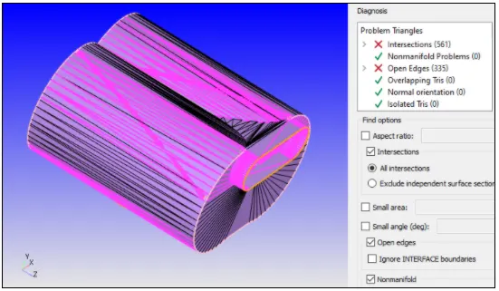
From the above image, we have eliminated the intersection error which was occurring between the casing face and lobe face but still, we can see the intersection error occurring this intersection is basically happening between the lobe outer surface and casing inner surface as shown in the above image to get rid of these errors we basically going to make our lobes little bit shrink by using scaling option so that we have should have a gap between the lobe outer surface and casing inner surface.
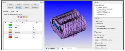
From the above plot, we have eliminated all the errors also we did the boundary flagging.
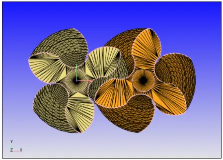
Also, in the below we can see the components of the supercharger more clearly
Supercharger
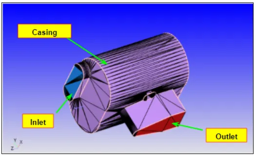
Lobes
Case Setup:
- Application: General Flow
- Solver: Transient solver
- Simulation Type: Gas
- Material: Air
- Simulation mode: Full hydrodynamic
Simulation time parameters:
- Start time:0 sec
- End time:0.01 sec
Region & Initialization:
In this step, we have created a region of the fluid and initialize the species value as follows:
- N2=0.77
- O2=0.23
Boundary Conditions:
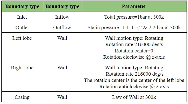
Over here in order to make the rotation center of the lobes much simpler we have bring the origin to the center of the left lobe so which means the left lobe will rotate in a clockwise direction & the center of rotation of the left lobe will its own center while the right lobe will rotate in an anticlockwise direction but the center of rotation of the right lobe will be the center of the left lobe
Physical Model
Turbulence model:k_e-epsilon
Grid Control:
- Element size:dx = 2e-3m, dy = 2e-3m & dz = 2e-3m
Output Files:
- The time interval for writing 3D output data files: 6e-05 sec (So, that we get at least 100 3D output files)
- The time interval for writing text output:1e-5 sec(So, that we get every minute )
- The time interval for writing restarting output:6e-05sec
- Maximum number of restart file saved:3
Post-Processing
No-Hydro simulation:
Mesh:
Total cell count:

From the above plot, we can say that there is little variation in the total cell count plot this is happening because of the rotation of the lobes also we can see the total cell count are almost the same for all the cases.
Mass convergence:
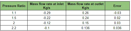
By looking at the above table we can say that mass is almost converged though the error is not in the give tolerance limit but we can achieve in order to do this we need to run the case with more refined & for the number of cycles
Performance plot:
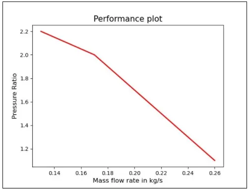
From the above plot, we can see that as pressure ratio increase mass flow rate increase
Contours:
When the pressure ratio is 1.1 bar
When the pressure ratio is 1.5 bar
When the pressure ratio is 2 bar
When the pressure ratio is 2.2 bar
From the above velocity & pressure contours, we can see that the velocity of the fluid between the lobes is high because of two reasons the first one is sudden area drop, and the second once because of compression meaning the fluid which is air over here getting compress between the lobes which increase the speed of the fluid & when the lobes rotate the fluid get stagnant at the inner surface of the supercharger which basically converting kinetic energy into pressure energy and this is the reason the pressure get increased at the outlet.
Comparing internal energy solver and total_energy_solver results
Temperature Plot
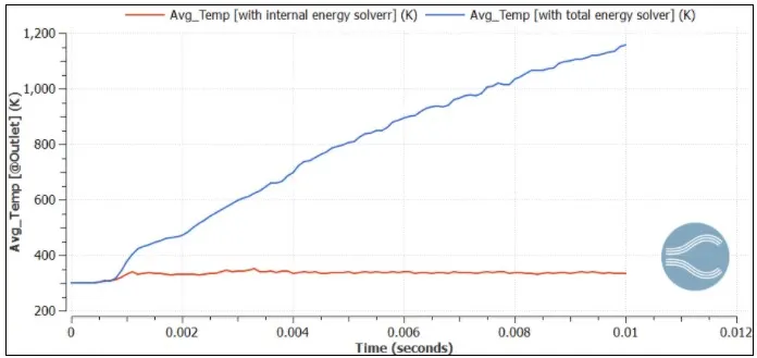
From the above plot, we can see that the temperature when we are using total energy solver this because in total energy solver the mechanical work is done on the fluid also comes into consideration and this leads to higher temperatures with total energy solver.
Conclusion:
- Successfully simulated supercharger with different pressure ratios in order to see its effects on the mass flow rate.
- The working principle behind & types of supercharger studied successfully