Week 12: Shell and Tube Heat Exchanger simulation
Aim: The objective of this simulation example is to analyze the heat transfer in a shell and tube heat exchanger configuration. The system would have water flowing through the shell and hot oil passing through the tubes.
Theory:
Hydroelectric power plants use the kinetic energy of water to produce electricity. The alternate current generated by the turbine is then converted to a high voltage current by the plant transformers. These transformers heat up due to hysteresis losses, so a cooling system is needed to control the transformer temperature. Some transformers are immersed in oil and use the available water resource for their cooling systems. Shell and tube heat exchangers are used for their compactness. The oil heats up as it comes in contact with the transformer core. Then, the oil flows in the shell side, dissipates heat to the colder water flowing on the side of the tube, and finally gets pumped back into the transformer.
Types of Heat Exchanger
The heat exchanger can also be classified based on flow arrangement which is as follows:
- Double pipe parallel-flow heat exchanger
- Double pipe counter flows heat exchanger.
- Crossflow heat exchanger.
Double pipe parallel flow & counter flow heat exchanger
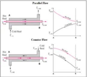
- The simplest heat exchanger is a double pipe heat exchanger that consists of a concentric tube moving in the same or opposite direction.
- If the fluids are moving in the same direction then this type of arrangement is called a parallel-flow heat exchanger.
- If the fluids are moving in the same direction then this type of arrangement is called a parallel-flow heat exchanger.
Cross Flow Heat Exchanger
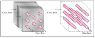
- The two-fluid can also move perpendicular to each other and this type of flow configuration is known as cross-flow heat exchanger..
- Crossflow heat exchangers can be further classified into two types as shown in the above figure.
Application:
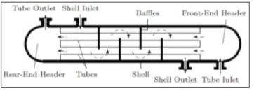
- One common type of heat exchanger in industrial applications is the shell-and-tube heat exchanger.
- It contains a large number of parallel tubes packed in a shell. Heat is exchanged as one fluid flows through the tubes while the other flows outside the tube through the shell.
- Baffles are placed in the shell to force the shell-side fluid to flow across the shell to enhance the heat transfer and to support and maintain uniform spacing between the tubes.
Baffle: Baffles are mainly used in industrial process vessels or tanks such as heat exchangers etc. The baffle is actually an obstructing vane or panel mounted inside the vessel wall. The main purpose of the vessel wall is to reduce the tangential fluid velocity by a mixing impeller. This enhances the mixing efficiency of the fluid within the vessel results by vigorous top to bottom mixing. In absence of baffle, the time required to achieve the desired mixing is more or sufficient blending of fluids does not become possible abruptly. In the case of heat exchangers baffle not only enhances the heat transfer coefficient but also helps in supporting the tube bundle inside the shell and tube heat exchanger. Baffles are placed in shell and tube heat exchanger such that they can give direction to the fluid flow.
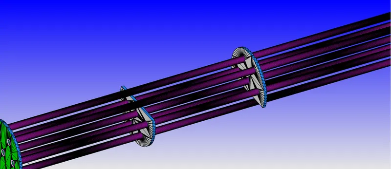
There are several reasons for using baffles in the heat exchanger, below is a list of functions that baffles are often used for
- To support tubes in the heat exchanger
Tubes must be supported at intervals not more than 1.5m; this mainly depends on the diameter of the tube and the material of construction. The support intervals can be shorter where flow-induced vibrations occur in certain operations.
Supporting the tubes in baffles also prevent mechanical vibrations that can result in tube touching each other and giving rise to leakages and failures mainly near tube sheets.
- To enhance the heat transfer by directing the flow through the shell in the desired pattern
This also increases turbulence and reduces the stagnant pockets in the heat exchanger. We can also maintain a desired velocity by introducing baffles.
Types of baffles in the heat exchanger
There are different types used in heat exchangers, below are the popular ones.
Segmental baffles: A plate type baffles may be a single segmental, double segmental, or triple segmental. The single and double segmental baffles are most frequently used as they diver the flow most effectively across the tubes.
Disk and doughnut baffle: Has alternating outer rings and inner disk which directs the flow radially across the tube field. They all very effective in pressure drop to heat transfer conversion.
Orifice baffle: In this type of baffles the shell side fluid flows through the clearance between the tube outside diameter and the baffle hole diameter.
Rod baffle:
- This type is metal rods rather than metal plat baffles. The type is used wherever a very low-pressure drop is required. Rob baffles also estimate the tube variations which occur with plate baffles when fluid velocities are high.
- The flow in the shell side is mainly parallel to the tube axis. Tubes are arranged with square pitch. Rods, with a diameter equal to the clearance between the tube rows, are attached to ring supports and placed between alternate tubes in both horizontal and vertical directions.
- Rod baffles are mainly used when the pressure drop available is very low or there is a pressure drop issue.
Baffle cut:
- This term is normally expressed in the percentage of the shell inside diameter that is no covered by a baffle, and is defined as the height of the segment that is cut in each baffle to allow the shell side fluid to flow across the baffle.
- The normal recommended value of 20% to 25% cut of shell diameter is used in shell and tube heat exchanger design, the larger the cut the lower the pressure drop however it comes with a disadvantage on the heat transfer as the poorly distributed flow with large eddies is produced causing stagnant areas or dead spaces behind the baffles in the shell, this result in lower heat coefficient. With a smaller cut, the percentage drop is higher and the heat transfer coefficient is also higher.
- The baffle cut orientation can differ from horizontal cut and vertical cut and varies between 15% and 45% if the shell inside diameter with 45% being a maximum cut for single segmental baffles. Reducing the baffle cut below 20% to increase the shell side heat transfer coefficient or increasing the baffle cut beyond 35% to decrease the shell side pressure drop usually leads to poor design.
Geometry:
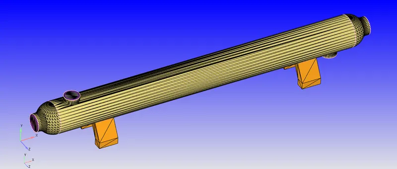
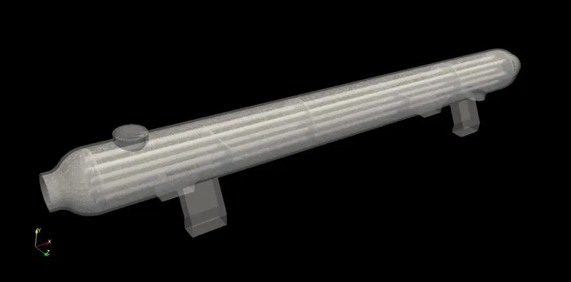
The pre-modeled geometry was imported into Converge and the geometry was inspected for surface error or other errors. After fixing all the errors & the boundaries were flagged & the case was set up.
Shell & Tube Heat exchanger
Case Setup:
- Application: General Flow
- Solver: Transient solver
- Simulation Type: GAS & Liquid
- Fluid Material:
- Species on Shell side Fluid is: Ethylene Glycol Oil (C2H6O2) this is hot fluid
- Species on Tube side Fluid is Water (H2O) this is cold fluid
- Solid Material: Copper
- Simulation mode: Full hydrodynamic
Simulation time parameters:
- Start time:0 sec
- End time: 1.5 sec
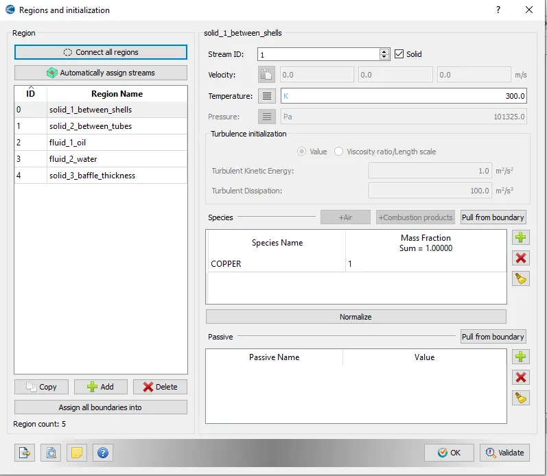
Region & Initialization:
In this step, we have created a region of the fluid.
Physical Model
Turbulence model:k_e-epsilon
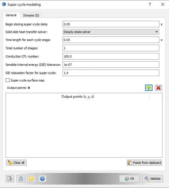
Super cycling:
Grid Control:
- Element size:dx, dy & dz =0.01m
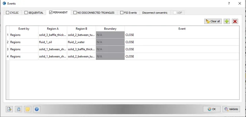
Events:
We have created the following permanent events.
CASE SETUP:
Plots for Parallel flow are as follows:
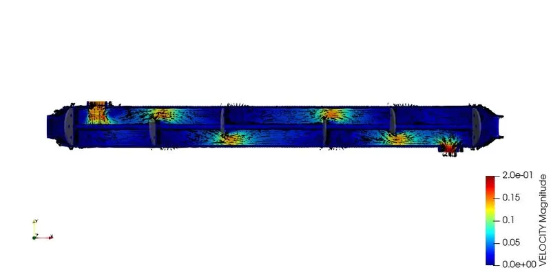
Velocity:
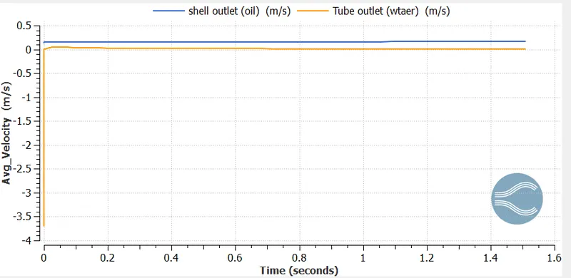
From the above plot:
- Velocity of Cold fluid (v_c)=0.019m/s
- Velocity of Hot fluid (v_h)=0.146m/s
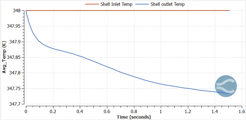
Shell Side Temperature:
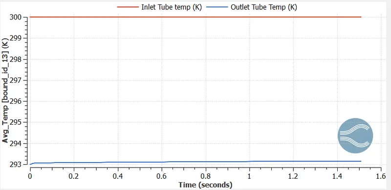
Tube side Temperature:
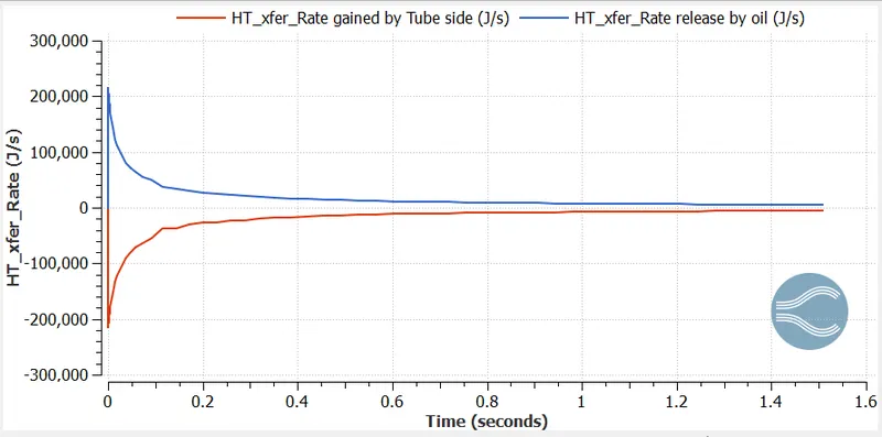
Total Heat transfer between oil and tube:
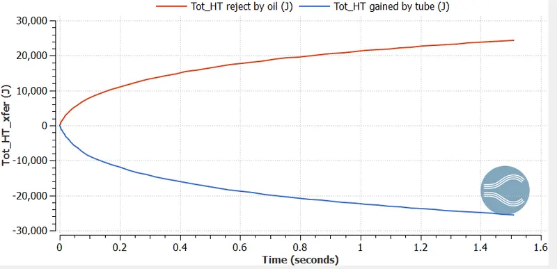
Heat transfer rate between oil and tube:
Calculation:
Given Data:
Tube side fluid à Water (H2O) à COLD FLUID
- Temperature of cold fluid at inlet (T_ci) = 20° C
- Temperature of hot fluid at inlet (T_hi) = 75° C
- Outer Diameter of Tube(d_o) = 23 mm
- Inner Diameter of Tube (d_i) = 20 mm
- h_i = 4500 W/(m^2-K)
- h_o = 1250 W/(m^2-K)
- Length of tubes (l) = 2.4 m
- C_(p(H2O)) = 4200 J/(Kg-K)
- C_(p(C2H6O2)) = 2600 J/(Kg-K)
- Number of tubes (n) = 7 tubes
- Mass flow rate of cold fluid = 1.162 kg/s
- Mass flow rate of hold fluid = 1.252 kg/s
To Find:
LMTD (Log Mean Temperature Difference)
From data:
`T underset(ci)()=20^oC` & `T underset(hi)()=75^oC`
From above Temperature plot:
`T underset(co)()=27^oC` & `Tunderset(ho)()=74.7^oC`
At Inlet:
`DeltaT=Tunderset(hi)()-Tunderset(ci)()`
`DeltaTunderset(i)()=75-20=55^oC`
At Outlet:
`DeltaT=Tunderset(ho)()-Tunderset(co)()`
`DeltaTunderset(o)()=74.7-27=47.7^oC`
LMTD
`DeltaTunderset(m)()=frac{DeltaTunderset(i)()-DeltaTunderset(o)()}{ln(frac{DeltaTunderset(i)()}{DeltaTunderset(o)()})`
`DeltaTunderset(m)()=frac{55-47.7}{ln(frac{55}{47.7})`
`DeltaTunderset(m)()=51.26^oC`
Heat Transfer Rate:
`Q=m underset(h)()xxCunderset(h)()xxdtunderset(h)()`
`Q=1.252xx2600xx(75-74.7)=976.56W`
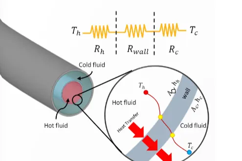
Overall Heat transfer coefficient:
Formula:
`Q=Uunderset(o)()Aunderset(s)()DeltaTunderset(m)()`
`976.56=Uunderset(o)()xxpixxdunderset(o)()xxnxxLxx51.26`
`Uunderset(o)()=15.69 (W)/(m^2K)`
Geometry:
- Velocity Contour:
- Velocity Animation:
Plots for Counter flow are as follows:
Velocity:
From the above plot:
- Velocity of Cold fluid (v_c)=0.019m/s
- Velocity of Hot fluid (v_h)=0.146m/s
Shell Side Temperature:
Tube side Temperature:
Total Heat transfer between oil and tube:
Heat transfer rate between oil and tube:
Calculation:
Given Data:
Tube side fluid à Water (H2O) à COLD FLUID
- Temperature of cold fluid at inlet (T_ci) = 20° C
- Temperature of hot fluid at inlet (T_hi) = 75° C
- Outer Diameter of Tube(d_o) = 23 mm
- Inner Diameter of Tube (d_i) = 20 mm
- h_i = 4500 W/(m^2-K)
- h_o = 1250 W/(m^2-K)
- Length of tubes (l) = 2.4 m
- C_(p(H2O)) = 4200 J/(Kg-K)
- C_(p(C2H6O2)) = 2600 J/(Kg-K)
- Number of tubes (n) = 7 tubes
- Mass flow rate of cold fluid = 1.162 kg/s
- Mass flow rate of hold fluid = 1.252 kg/s
To Find:
LMTD (Log Mean Temperature Difference)
From data:
`T underset(ci)()=20^oC` & `T underset(hi)()=75^oC`
From above Temperature plot:
`T underset(co)()=27^oC` & `Tunderset(ho)()=74.7^oC`
At Inlet:
`DeltaT=Tunderset(hi)()-Tunderset(ci)()`
`DeltaTunderset(i)()=75-20=55^oC`
At Outlet:
`DeltaT=Tunderset(ho)()-Tunderset(co)()`
`DeltaTunderset(o)()=74.7-27=47.7^oC`
LMTD
`DeltaTunderset(m)()=frac{DeltaTunderset(i)()-DeltaTunderset(o)()}{ln(frac{DeltaTunderset(i)()}{DeltaTunderset(o)()})`
`DeltaTunderset(m)()=frac{55-47.7}{ln(frac{55}{47.7})`
`DeltaTunderset(m)()=51.26^oC`
Heat Transfer Rate:
`Q=m underset(h)()xxCunderset(h)()xxdtunderset(h)()`
`Q=1.252xx2600xx(75-74.7)=976.56W`
Overall Heat transfer coefficient:
Formula:
`Q=Uunderset(o)()Aunderset(s)()DeltaTunderset(m)()`
`976.56=Uunderset(o)()xxpixxdunderset(o)()xxnxxLxx51.26`
`Uunderset(o)()=15.69 (W)/(m^2K)`
Geometry:
Velcoity Contour:
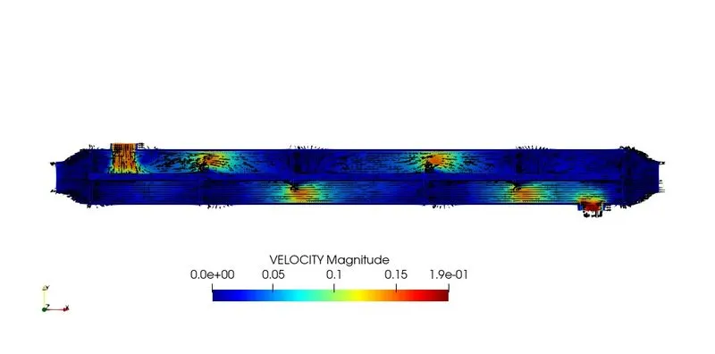
Animation:
Drawbacks of shell and tube heat exchanger:
- Heat exchanger effectiveness is less.
- Cleaning and maintenance are troublesome since a tube cooler requires enough clearance at one end to remove the tube nest.
- The capacity of the tube cooler cannot be increased.
- Requires more space in comparison to plate coolers
Fouling factors: We know the surface of the heat exchangers do not remain clean after it has been in use for some time. The surface becomes fouled with scaling or deposits. The effects of these deposits affecting the value of the overall heat transfer co-efficient. This effect is taken care of by introducing an additional thermal resistance called fouling resistance.
CONCLUSION:
So, the simulation process of shell and tube heat exchanger is done with both counter and parallel flow. The results show that the counter flow is better than the parallel flow.