Centrifugal pump design and analysis
OBJECTIVE
- Run the parametric study of a centrifugal pump for different velocity at outlet
- Plot the pressure ratio vs mass flow rate
THEORY:
A centrifugal pump is a mechanical device designed to move a fluid by means of the transfer of rotational energy from one or more driven rotors, called impellers. Fluid enters the rapidly rotating impeller along its axis and is cast out by centrifugal force along its circumference through the impeller's vane tips
PROCEDURE:
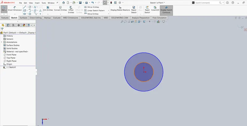
- Draw the 2 circle at different radius draw the circle at top plane
- Now use the arc tool to draw the plates
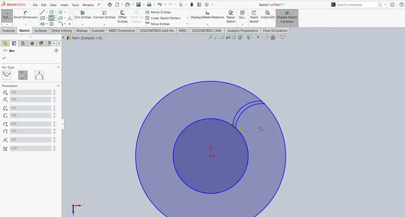
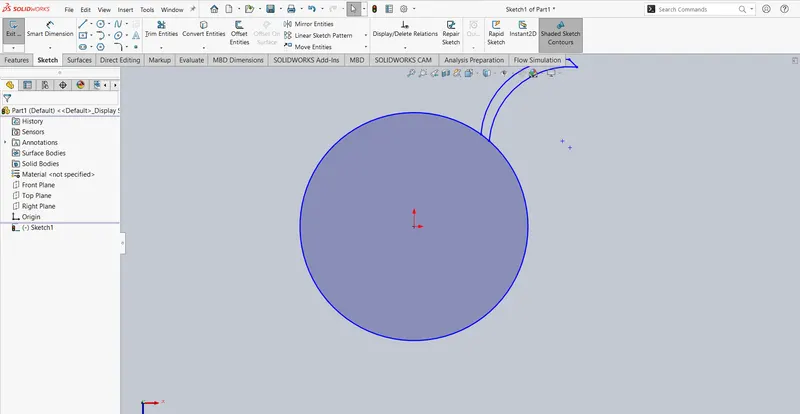
- Now do the trim for the circle
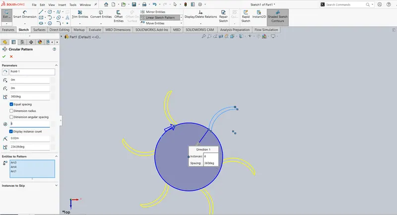
- Now do the circle pattern
- Now do the boss extrude to create impiller
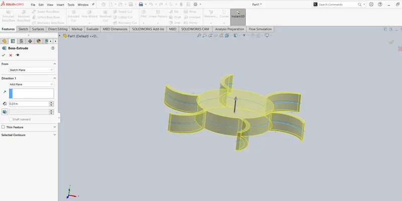
- Draw the circle
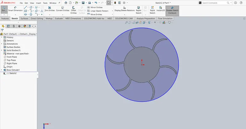
- Do the boss extrude
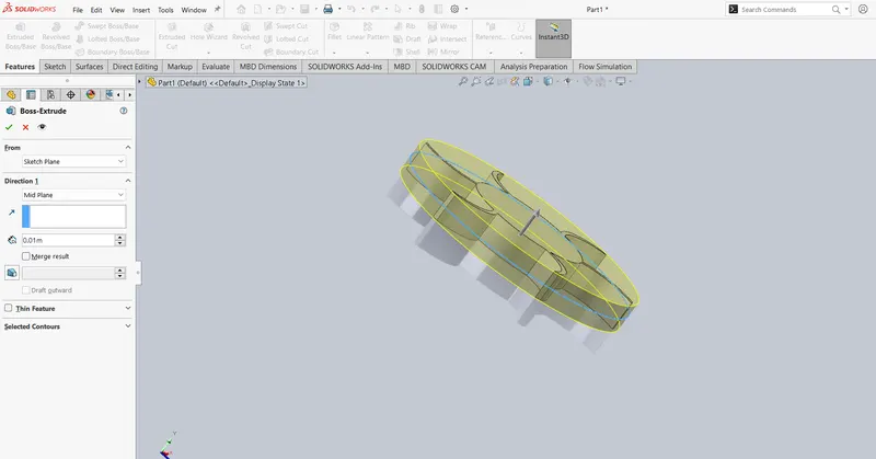
- Now the draw the caseing take new sketch on the top plane draw the circle
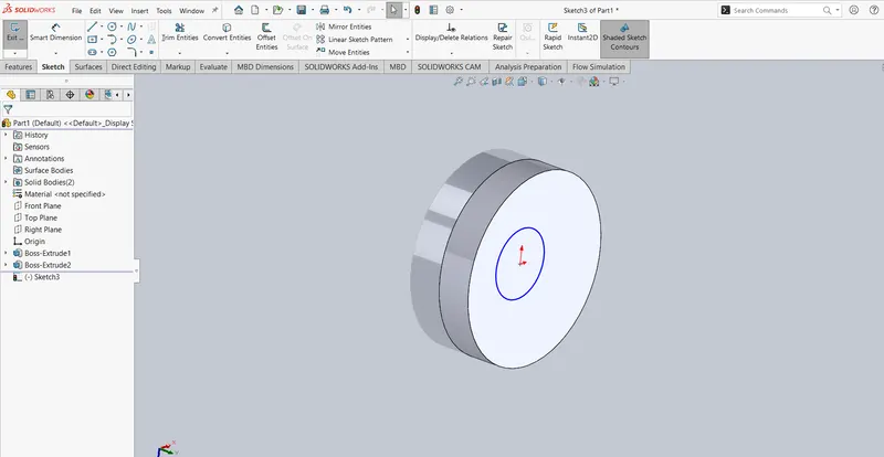
- Do the boss extrude
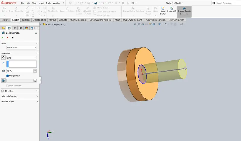
- Now draw the exit length take the new sketch on the top plane draw the lines
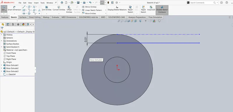
- Now to create the plane
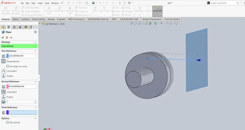
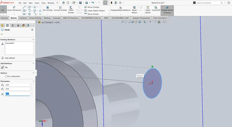
- Now create the sweep to create the sweep start the new sketch on the newly created plane draw the circle
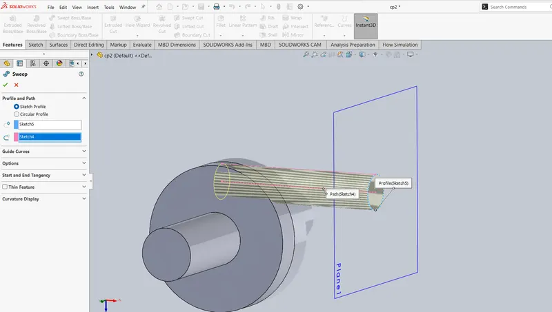
Flow Simulation Setup:
- save the model do the wizard process
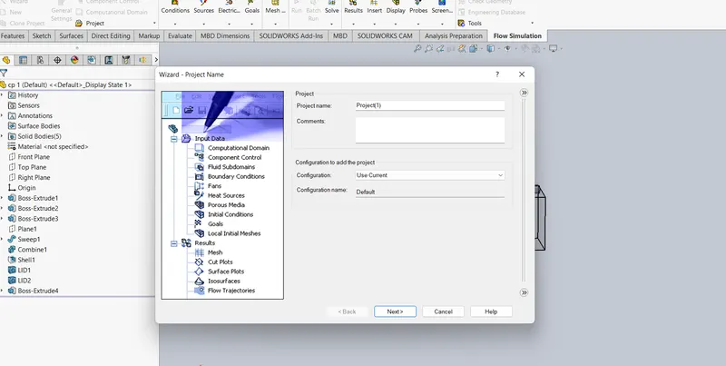
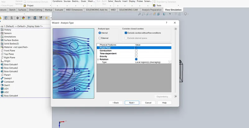
- Analysis type - Internal
- Rotation - Local region (averaging)
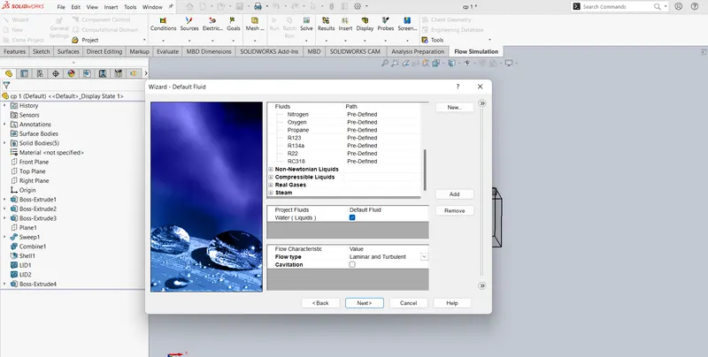
- Fluid - Water
- Flow type - Laminar and Turbulant
- Now add the rotating region
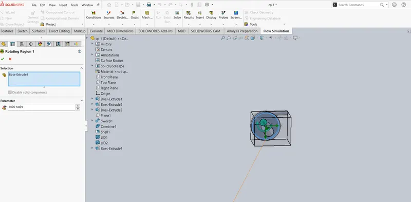
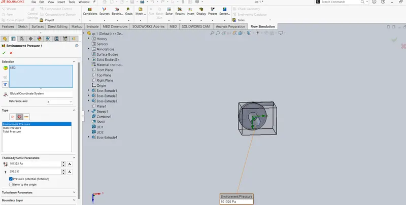
- Boundary Condition at Inlet - Enviornmental pressure
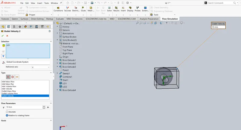
- Boundary Condition at Outlet - Velocity
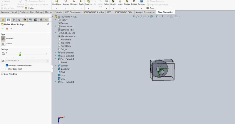
- Meshing (Advance channel refinement)
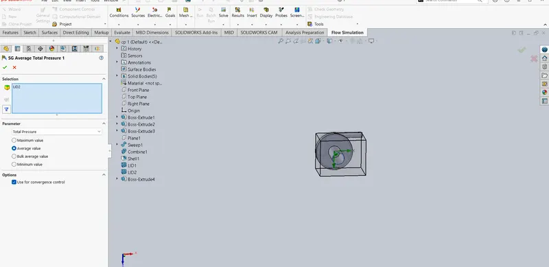
- Adding Goals (Total pressure at inlet)
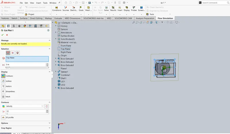
- Adding cutplots for velocity
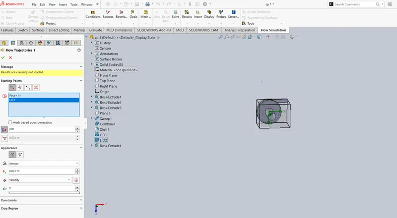
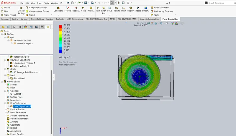
- Adding flow trajectory
- Now do the run
RESULT:
Cut Plot at 10
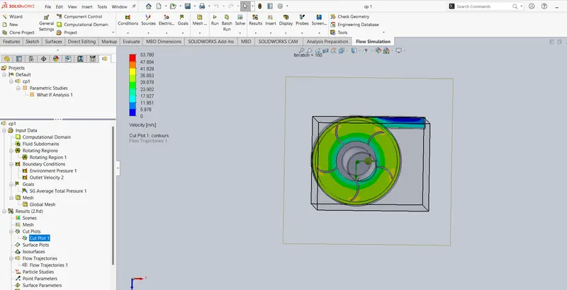
flow trajectories at 10
new parametric study
