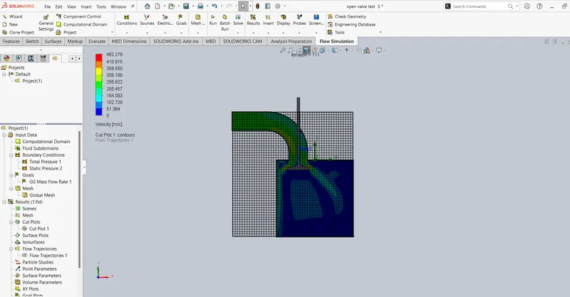
Modelling and simulation of flow through a flowbench
OBJECTIVE:
- To a Perform a Grid dependency test for a particular valve lift
- Perform a parametric study to determine the effect on the mass flow rate with different valve lifts
- Plot velocity cutplot for different valve lifts.
PROCEDURE:
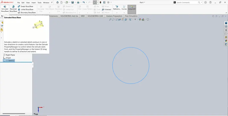
- Draw the Circle
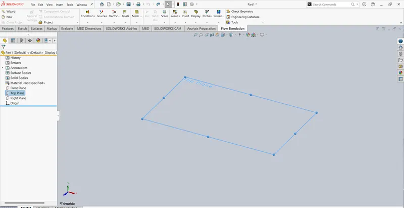
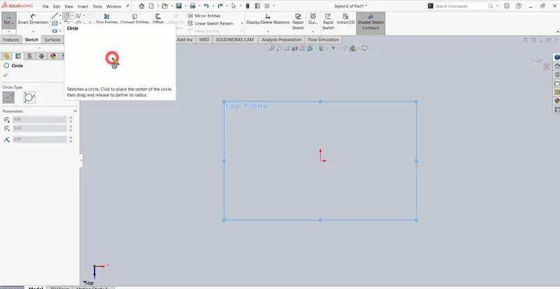
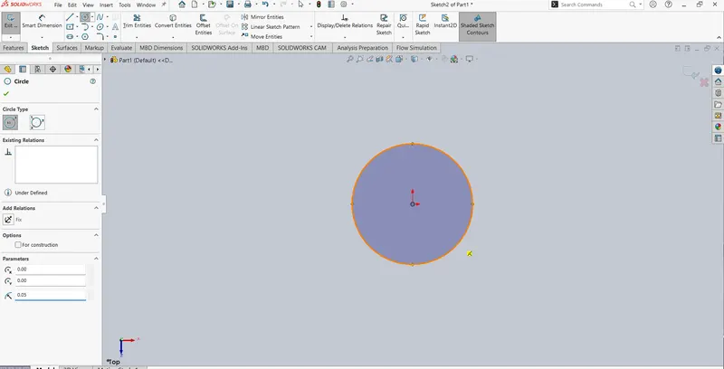
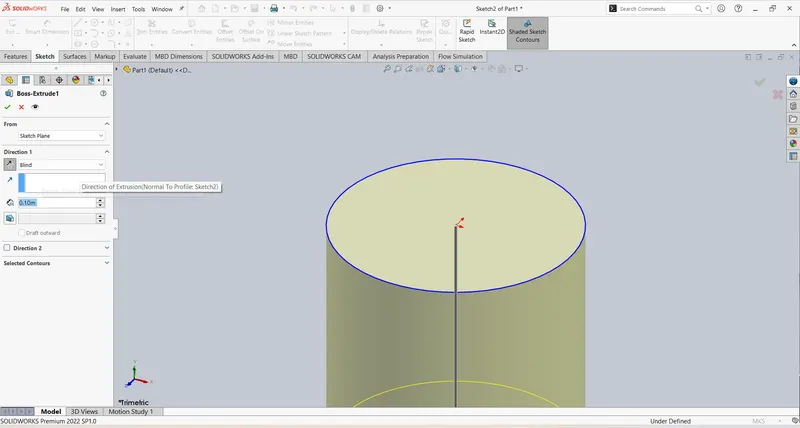
- Do the Boss Extrude
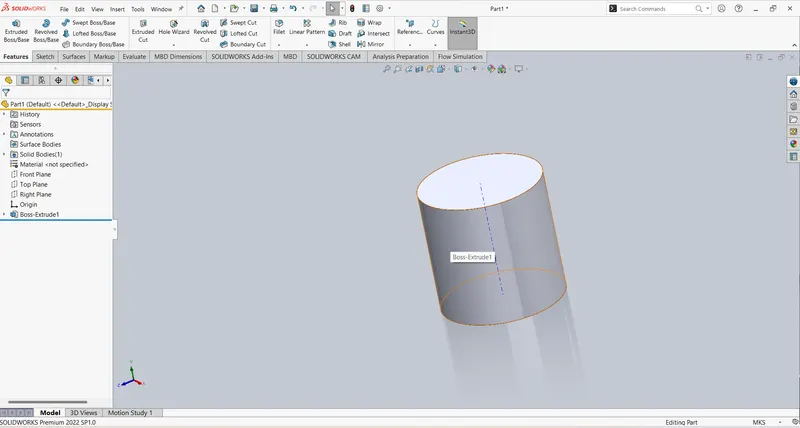
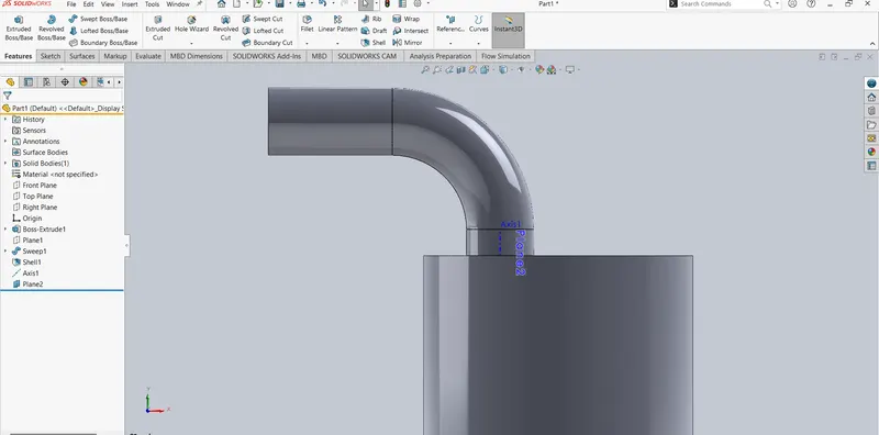
- Draw the Intake Port
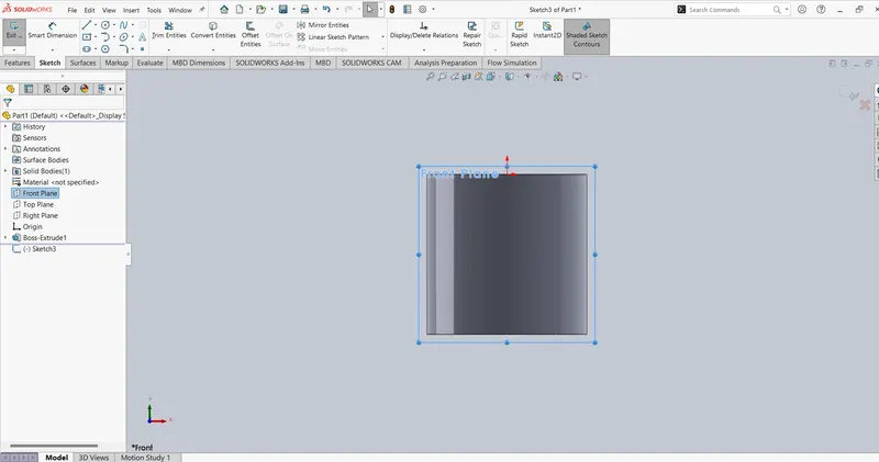
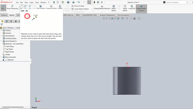
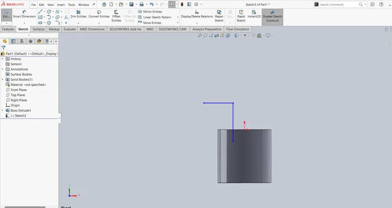
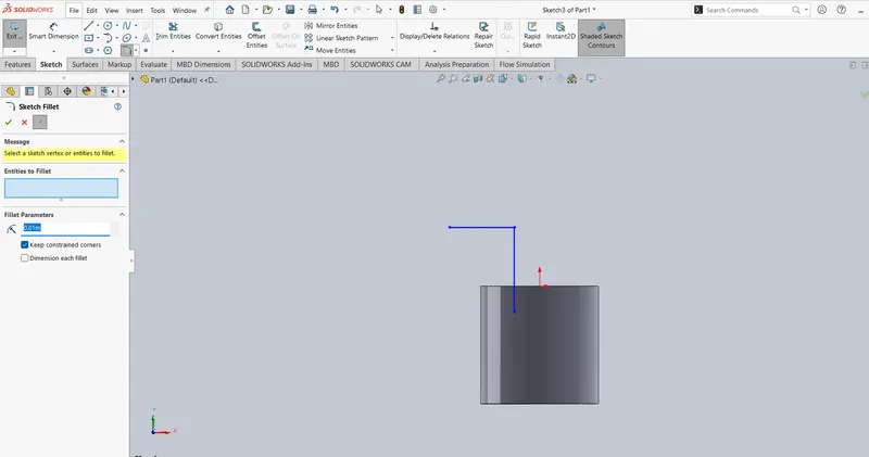
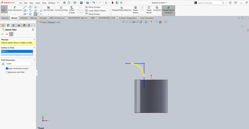
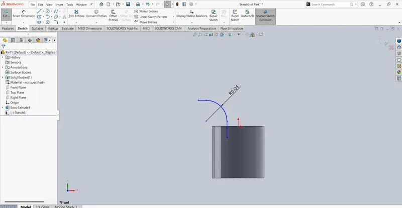
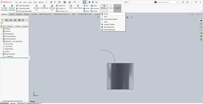
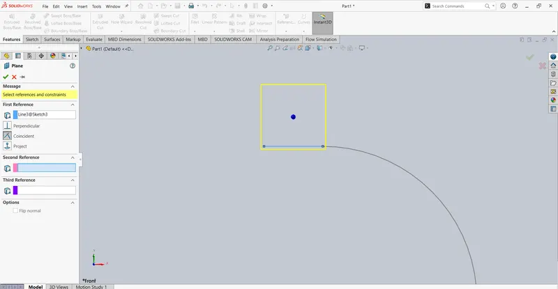
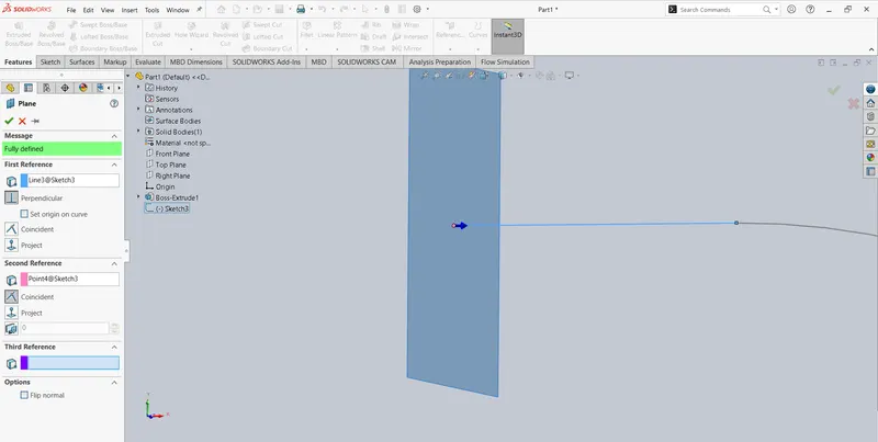
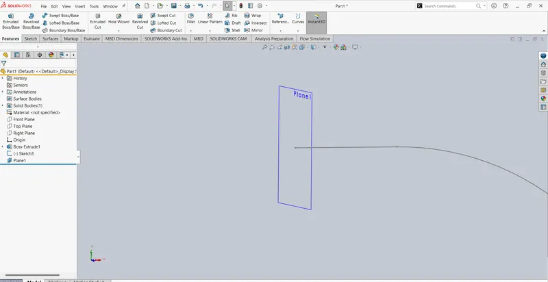
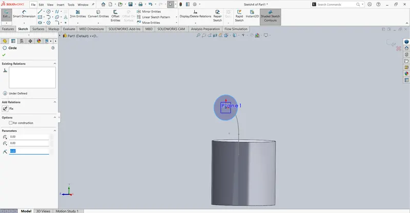
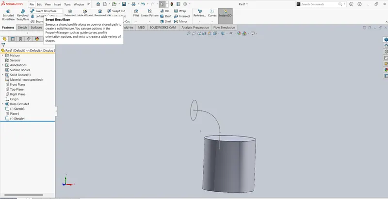
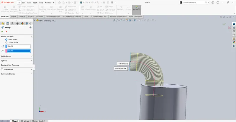
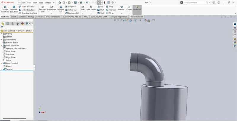
- Then the shell commend
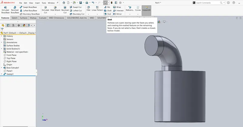
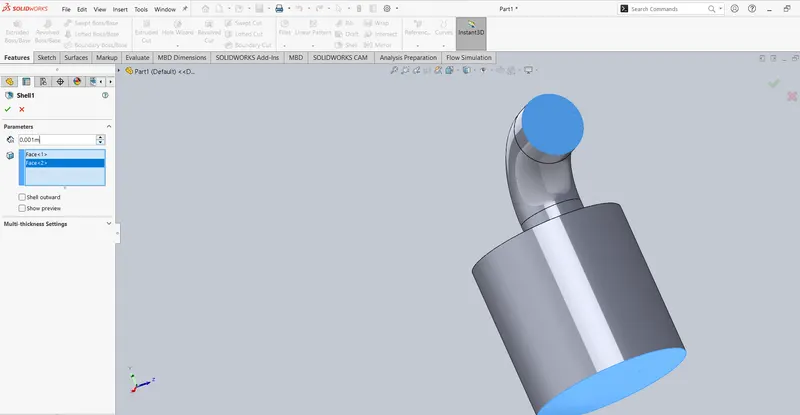
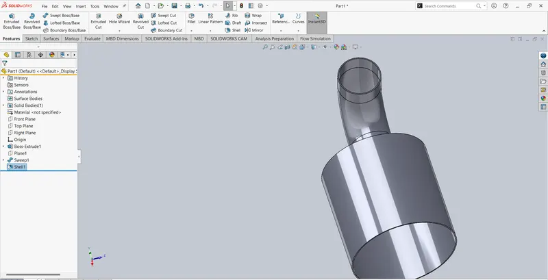
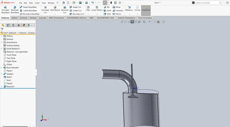
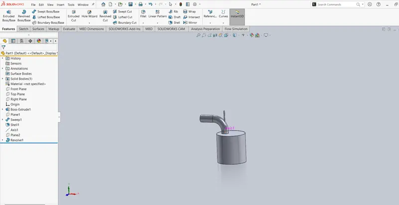
- Then create a valve
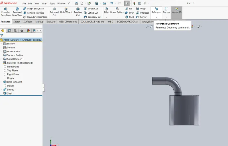
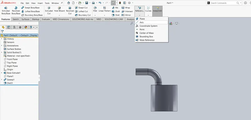
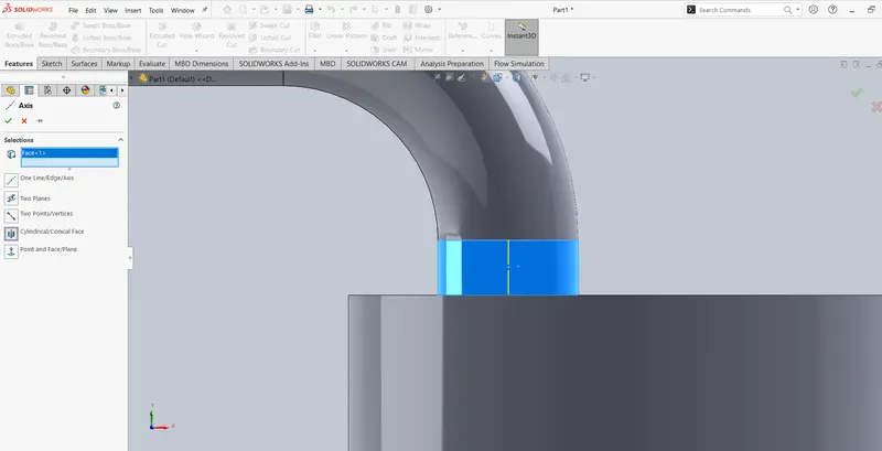
- To create valve first create the axis
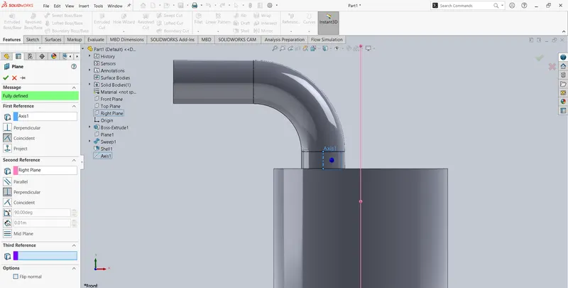
- Then create the plane
- Create sketch on the plane
- By using revolve option we create the valve
Flow Simulation:
- Wizard
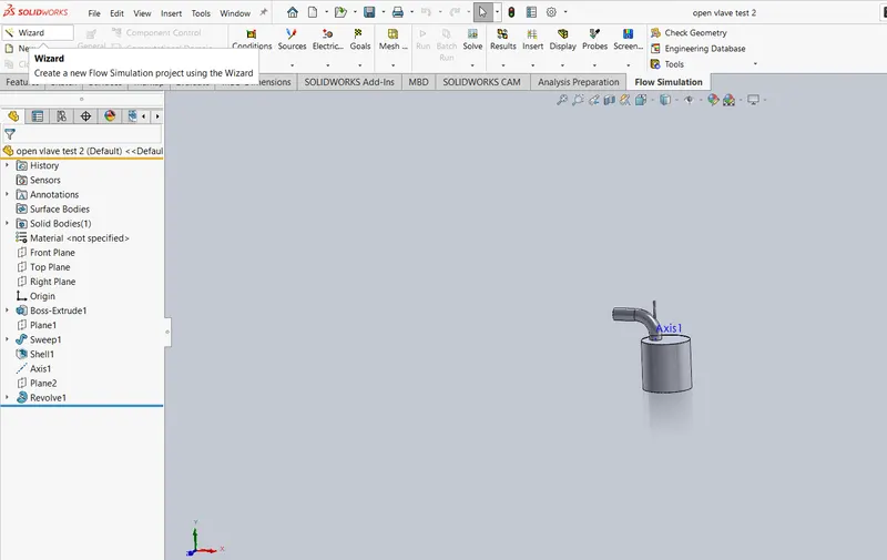
- Project name
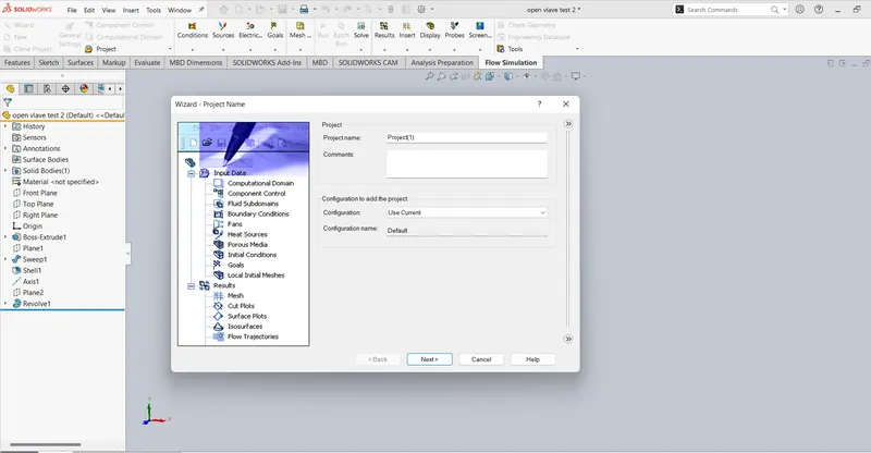
- Analysis Type - Internal
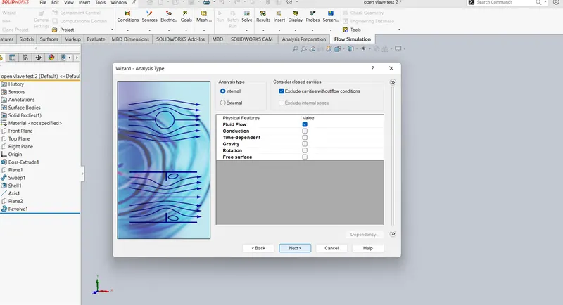
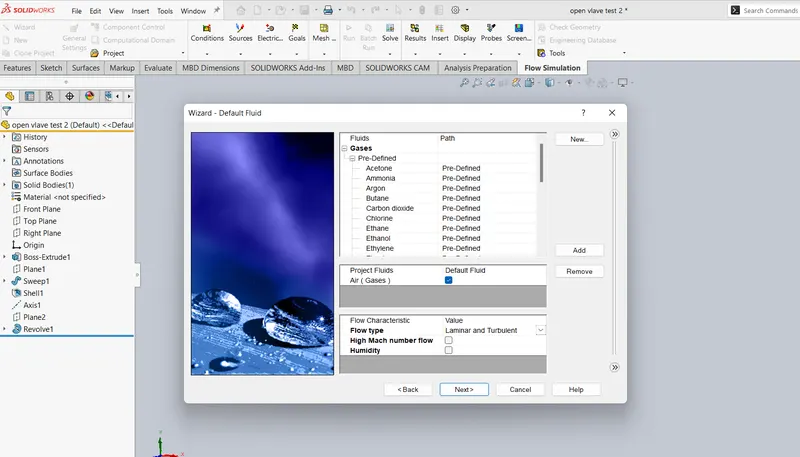
- Type of Fluids - Air
- Flow Type - Laminar and Turbulent
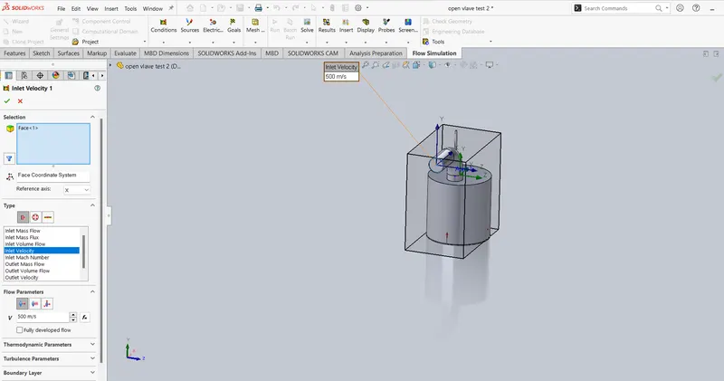
- Boundary condition at inlet
- Boundary condition at outlet
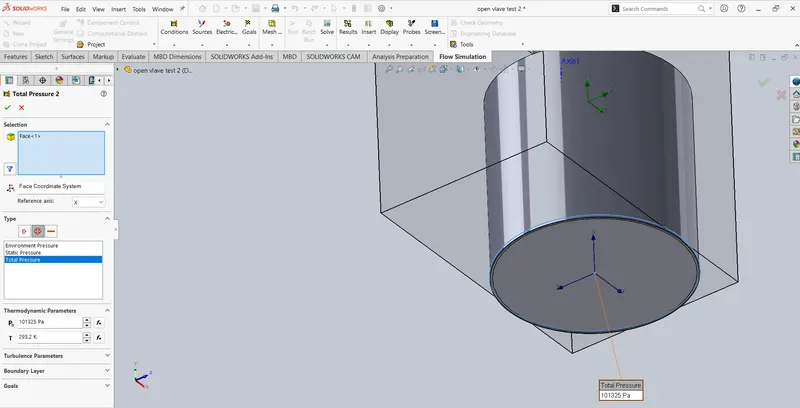
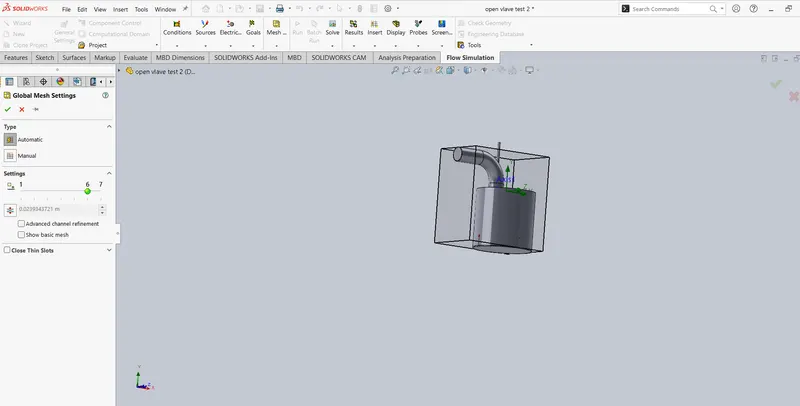
- Then apply the global mesh at (5,6,7)
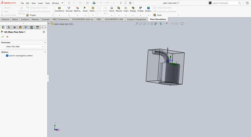
- Goals - SG mass flow rate
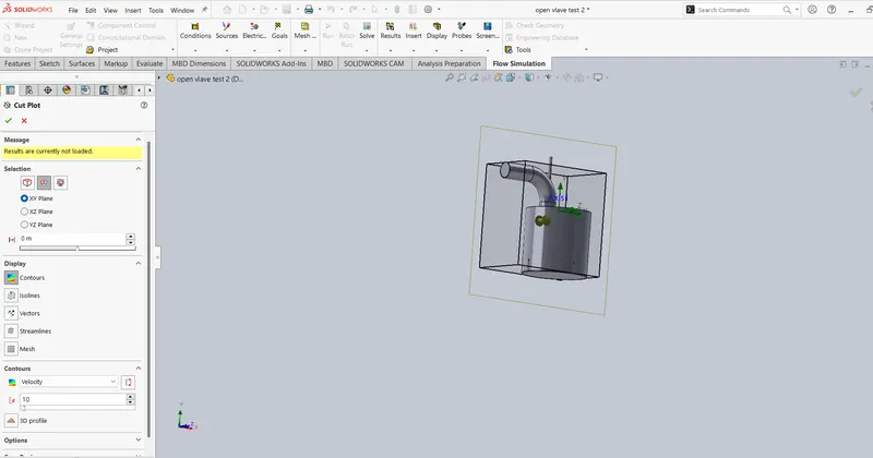
- Cutplot - velocity
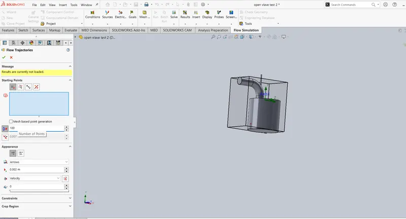
- Adding flow trajectory
Result:
Mesh at 5
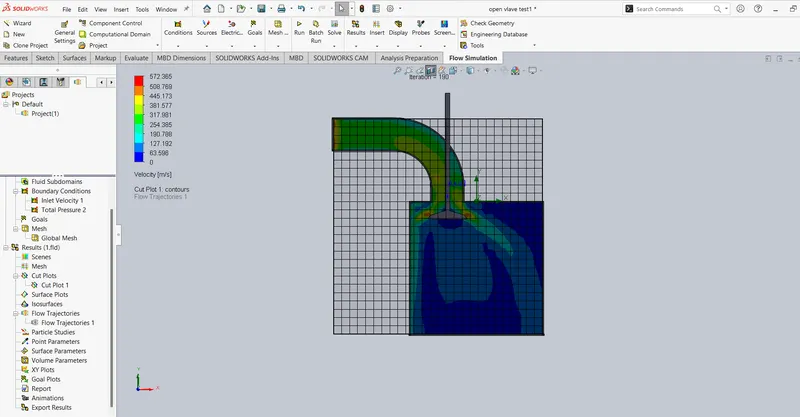
Mesh at 6
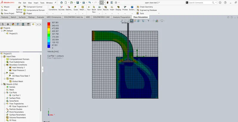
Mesh at 7