Bird Strike - Project - 2
AIM OF THE PROJECT
To perform a bird strike simulation when the bird tries to hit the gas turbine blade in LS-Dyna with kg/mm/ms as unit system.
BIRD STRIKE IMPACT
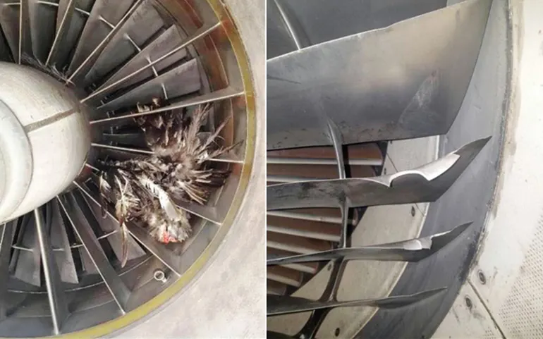
Bird strike is common and it can be a significant threat to aircraft industry. It is a collision between a bird and an aircraft. Old aircrafts and new aircrafts have suffered from bird strike. Jet engine ingestion occurs when the bird hits the jet engine of an aircraft and gets stucked in it. Given that the fan blades rotate at a high rpm, a bird strike on a fan blade causes its displacement into the adjacent blades. This leads to cascading failure, where in the entire system fails, there by resulting in a lot of damage.
The bird strike damage can be very severe and can shut down the engine as shown below. This is the behaviour we are trying to simulate for the damage done from the bird strike.
CONDITIONS REQUIRED
- The blades should rotate at a constant velocity but the casing should remain stationary.
- The cylindrical bird model should travel along its own axis and hit the blades.
- Use elastic material for the bird(2000MPa) and the casing(200GPa).
- The velocity of the engine blades and the birds can be chosen so that blade failure can be seen within a short span of time.
REQUIREMENTS OF THE PROJECT
-
Follow a consistent numbering approach 100000+ for nodes, 500000+ for elements, and 1000+ for the parts. All other keywords should be numbered within 10000-19999 while following a range for each one.
- The bird, casing, and the blades should be in different input files and there should be one main file referencing all the input files. The main file should contain only references. Control cards and boundary conditions should be there in another separate file. The reference include path should be such that the folder can be copied anywhere and it is able to correctly reference all the file and run the simulation.
PROCEDURE
Step 1: Import the model using keyword file using LS-PrePost
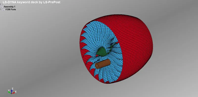
Brief description about the model
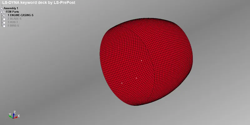
(a)Engine casing: It is the stationary part here and should not move from its location
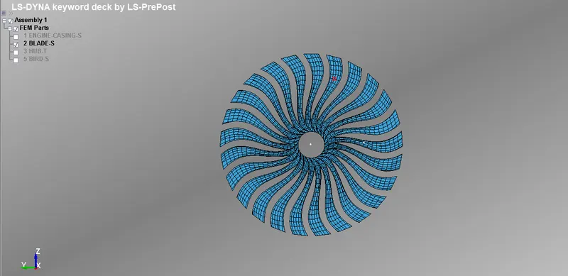
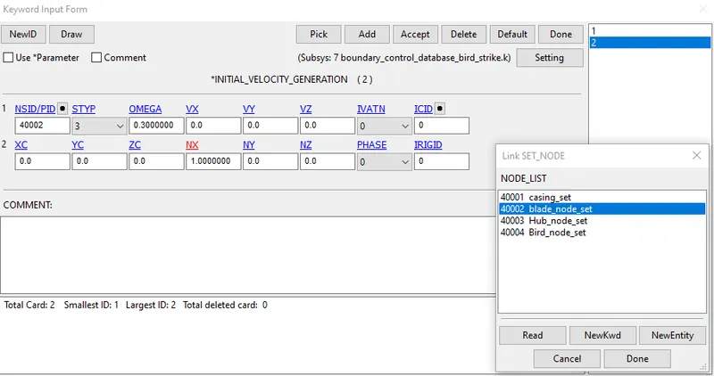
(b)Blades: In this project, blades are the main components. It should rotate with the angular velocity of 0.5 mm/ms and the material properties are slightly lower than the bird so as to break it earlier when the bird is making contact with the blade. The contact keyword is added to the blades part. This will allow the file not to penetrate with the adjacent blades.
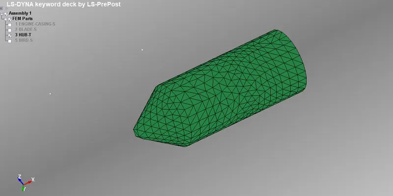
(c)Hub: The hub is the solid component and is meshed with the trias. The hub is connected with blades so that contact between blade and hub is not required. The hub will be rotated if the blades are rotating with respect to particular axis.
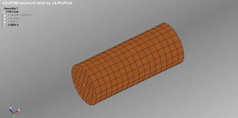
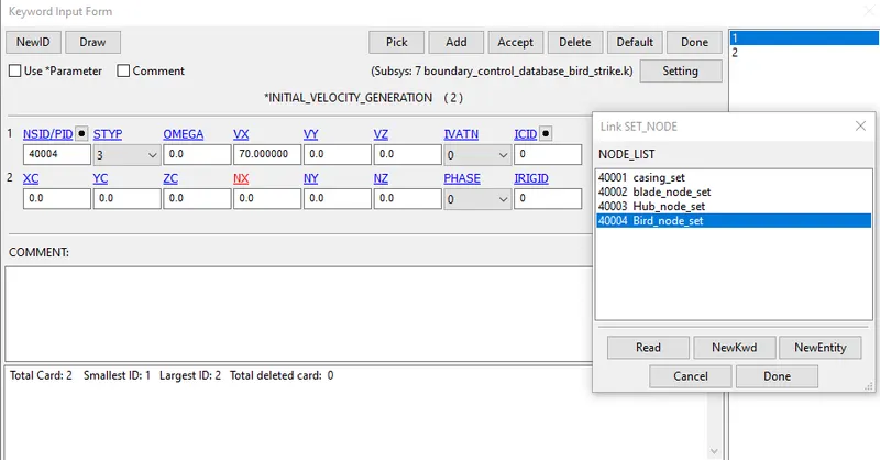
(d)Bird: It is the shell component which is provided with 20 mm/ms, when it is hitting the blades
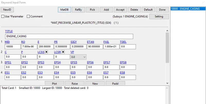
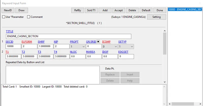
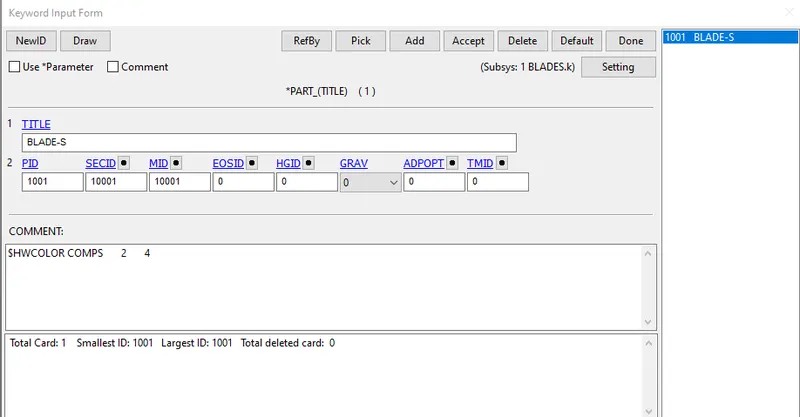
Step 2: Assign the material properties and section properties for each part as shown above
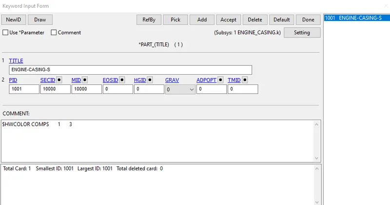
(a)Engine casing: Assign the material for engine casing as MAT_024. As given, Young's modulus for the casing material has to be kept for 200 GPa with all the other data assumed nearer to the properties of steel. FAIL value should be very large, tending not to fail. Section properties of shell element should be assigned to the casing with 5 mm thickness.
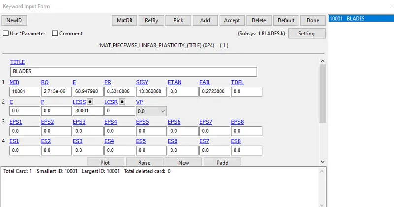
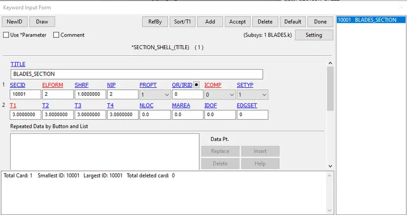
(b)Blades: Assign the material for blades as MAT_024. As we can see that E=68.94 GPa and FAIL=0.2723, which means the material will fail when it reaches 27.23% of the plastic strain value. Section properties of shell element should be assigned to the blades with 3 mm thickness.
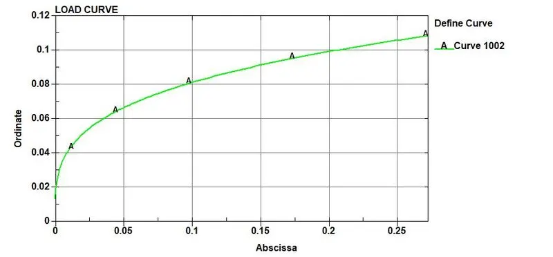
Definition of load curve: Below is the data of the material that we have input to the blade material card through LSID(12000)
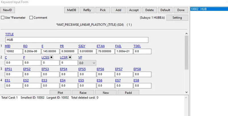
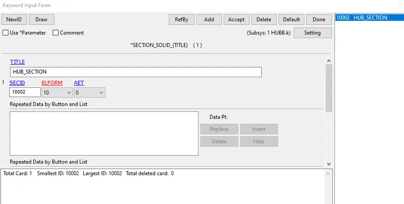
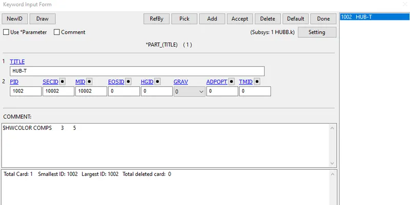
(c)Hub: Assign the material for hub as MAT_024. Young's modulus is assigned as 145 GPa and a high FAIL value. Section properties of solid element should be assigned to the hub with ELFORM as 10 for tetrahedron.
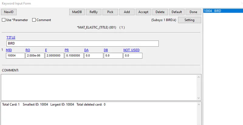
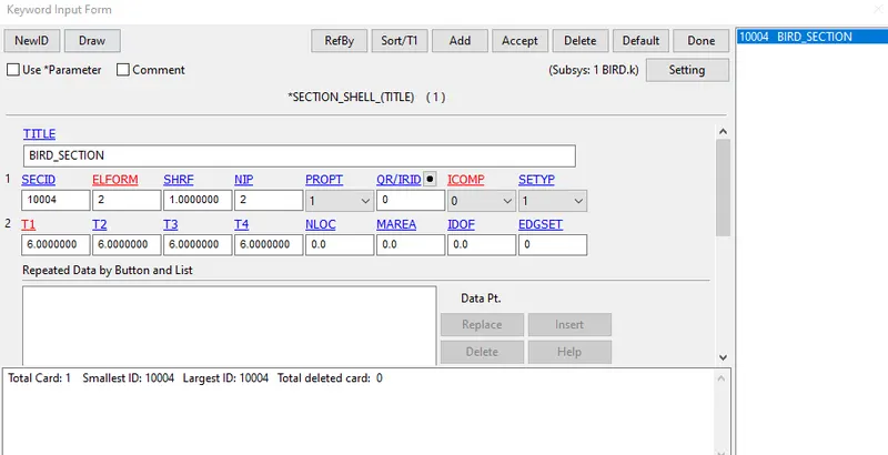
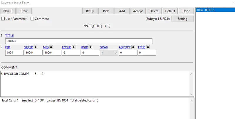
(d)Bird: Assign the material for bird as MAT_001. Young's modulus is taken as 2 GPa and Poisson's ratio as 0.15 and low density value as we need to replicate a bird into the simulation. It would be better if we represent a bird by Smooth Particle Hydrodynamic as it is a soft body impact in structural analysis. Section properties of shell element should be assigned to the bird with 6 mm thickness.
Step 3: Define boundary conditions to the associated parts
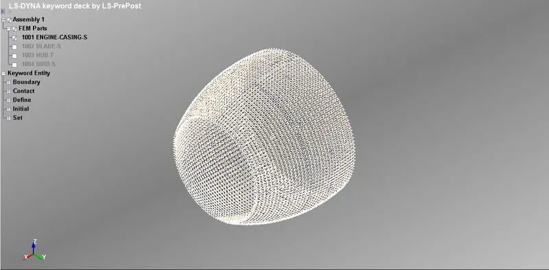
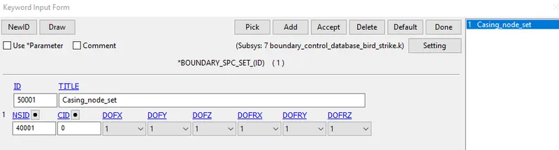
(a)Engine casing: Fix all the degrees of freedom of the casing nodes as shown below using Single Point Constraint
(b)Initial velocity generation for engine blade
(c)Bird: Assign the initial velocity generation of 20 mm/ms (70 Kmph) in X-Direction
Step 4: Define the contacts between the parts
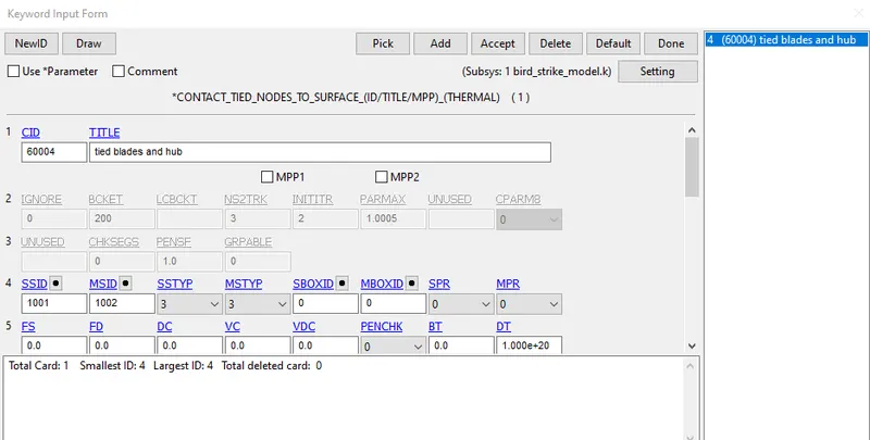
(a)Contact between hub and blade: *CONTACT_TIED_NODES_SURFACE is defined hub and the blade as it is an integrated unit and should rotate along with the blade at a similar angular speed. The master is assigned as hub and the slave is assigned as a blade
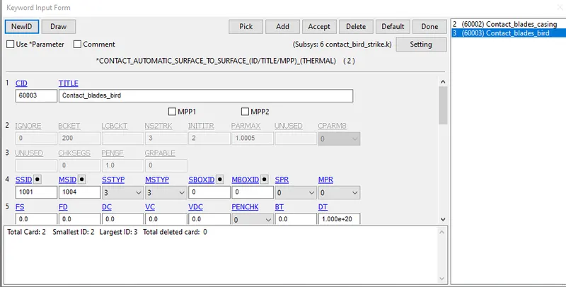
(b)Contact between blade and bird: *CONTACT_AUTOMATIC_SURFACE_TO_SURFACE is assigned between blade and bird interface with the master node as bird and slave node as blade
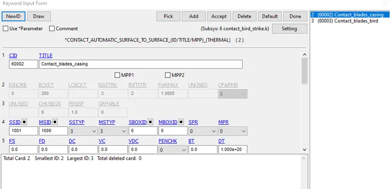
(c)Contact between blade and casing: *CONTACT_AUTOMATIC_SURFACE_TO_SURFACE is assigned between blade and casing interface with the master node as casing and slave node as blade
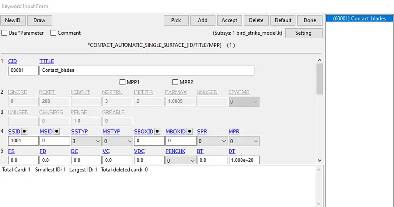
(d)Contact between the blades: *CONTACT_AUTOMATIC_SINGLE_SURFACE is defined for self contact between the blades with master node as zero and slave as a blade
Step 5: Define the database cards
(i) *DATABASE_BINARY_D3PLOT: It is used to get the outputs. Time step should be given as 0.1
(ii) *DATABASE_EXTENT_BINARY: It is used to compute elastic strain in the model and some of the strain data. STRFLG should be given as 1.
(iii)*DATABASE_ASCII: Load the value as 0.5 for GLSTAT, NODOUT and RWFORC under ASCII.
Step 6: Define control cards
(i)*CONTROL_ENERGY: Provide controls for energy dissipation options.
(ii)*CONTROL_TERMINATION: The end time of the simulation is specified as 4 ms. The purpose of this card is to stop the job.
(iii)*CONTROL_TIMESTEP: The purpose of this card is to set structural time step size control using different options.
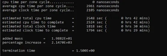
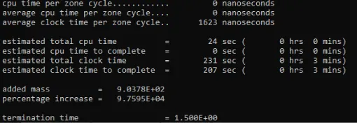
Control timestep card plays an important role in reducing the runtime. We can have a different combination of DT2MS and TSSFAC to check the estimate run time and percentage of mass added during mass scaling. Here we will try to keep the percentage of mass added below 7% and reduce the run time.
(a)In the first trial, D2TMS is loaded as -6e-05 and TSSFAC is loaded as 0.9. The estimated run time is 30 mins
(b)In the second trial, D2TMS is loaded as -6e-04 and TSSFAC is loaded as 0.9. The estimated run time is 04 mins
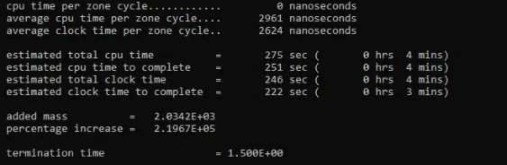
(b)In the third trial, D2TMS is loaded as -4e-04 and TSSFAC is loaded as 0.9.The estimated run time is 03 mins
Step 7: Include all the cards into the main file using *INCLUDE and run it
RESULTS
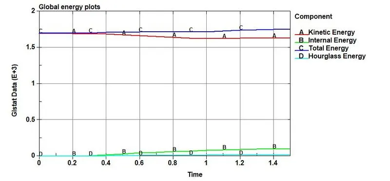
(i)Energy plots
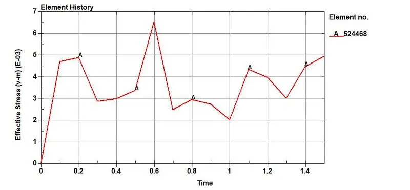
(ii)Von-Mises stress plots
(iii)Plastic strain plot

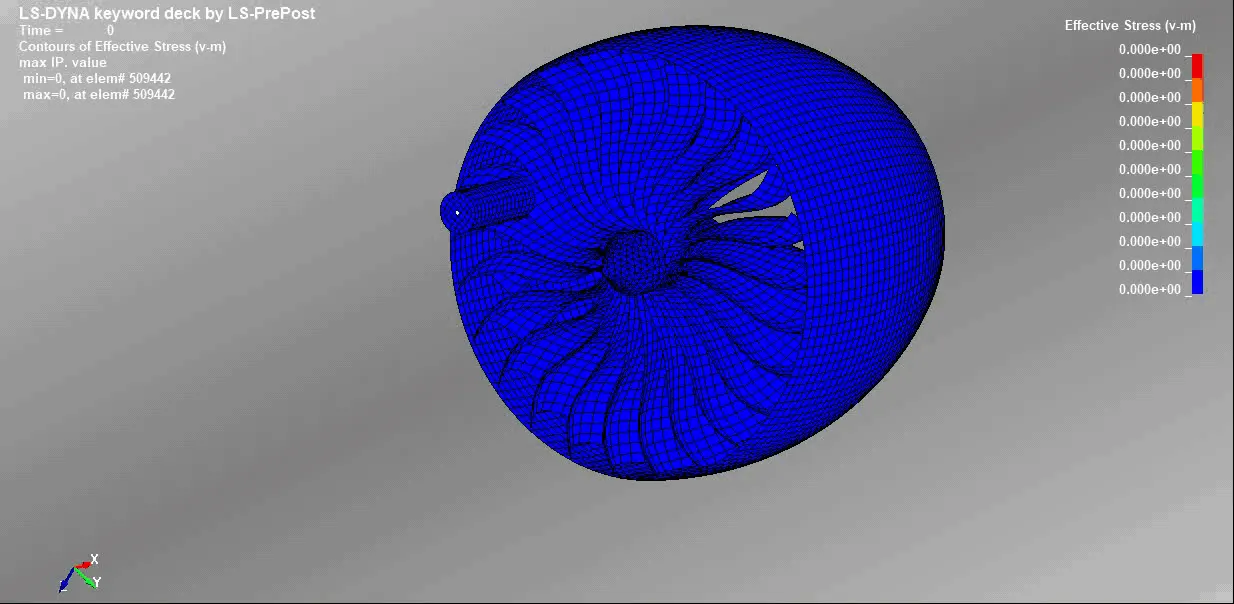
(iv)Contour of Von-Mises stress
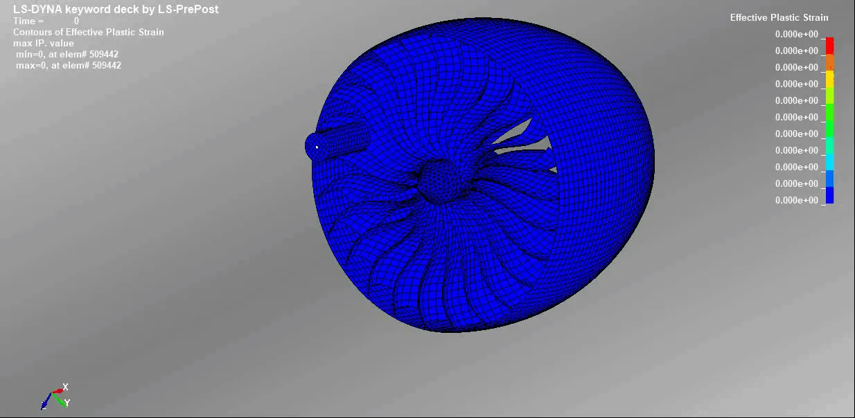
(v)Contours of Effective Plastic strain
CONCLUSION
- The keyword file to simulate bird strike on an aero engine is created by necessary conditions and requirements
- From the energy plot it is observed that the total energy is constant over the simulation
- The resuls and simulation is almost relatable what is happening in real time incidents
- The blades at the impact zone are damaged in the simulation
- The initial keyword files were debugged to get a realistic simulation of bird strike phenomenon