Week - 9 Material Modeling from Raw Data
AIM OF THE PROJECT
- To create a material model using the data extracted from the given true stress-true strain curve of graphite iron casting.
- Use a data digitizer to create the data points from the given curve
- Validate the material model by performing a tensile test on a dog bone specimen
GIVEN DATA
- Young's Modulus of graphite iron casting is 20.9e+06 psi. This is equivalent to 144 GPa
- To use kg-mm-ms unit system through out the project
THEORY
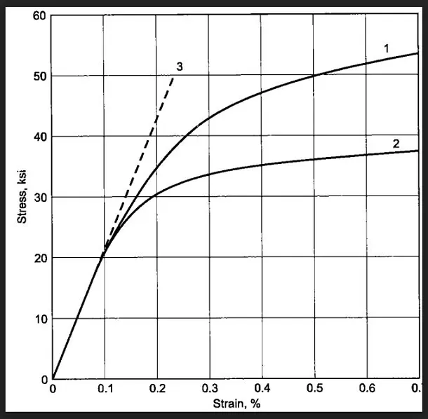
A stress-strain curve for graphite iron casting have been given in the problem. Two curves with different material structures have been shown. This response should be captured by either MAT_024(Piecewise linear plasticity) or MAT_018(Power law of plasticity) material model according to probelm statement
- MAT_018: In this material model, the eleastic-plastic behavious of the material is defined by power law of hardening. This is an isotropic material model. The stress-strain relation is defined by following equation
σy = kεn
σy = Yield strength
k = strength co-efficient
εn = total strain
n = hardening co-efficient
Therefore, the above equation is used to predict stress-strain behaviour of elastic-plastic material
- MAT_024: This material model also models the elastic-plastic behaviour of the material. Here the material behaviour can be treated as bi-linear stress-strain curve or multi-linear curve by defining a set of stress-strain points. The multi-linear behaviour can also be treated by defining a load curve in terms of effective stress versus effective plastic strain. The basic input material parameters for this model are mass density, yield stress, Poisson's ratio, Young's modulus and tangent modulus. Bi-linear stress-strain curve is the simplest form of representation and it captures the behaviour more accurately. So the basic concept here is the continuous smooth stress-strain curve is approximated with small linear steps.
PROCEDURE FOR MATERIAL MODELLING
Following are the steps which is to be followed to create a material model
- Data Extraction from the curve image
- Data clean up - Curve fitting
- Data/unit conversion
- 0.2% Offset yield strain
- Defining engineering stress/strain curve for the model
- Tensile test - Preprocessing
- Results and Validation
1)Data Extraction from the curve image: The given image file(jpeg) of true stress-true strain curve of graphite iron casting is opened in data digitizer software to extract the data and export it as an excel file. Any of the two curves should be chosen to extract data for true stress and true strain of graphite iron casting. Here, curve 2 is used through out the project. Make sure the data points picked is evenly spaced, so as to get smooth curve and better convergence.
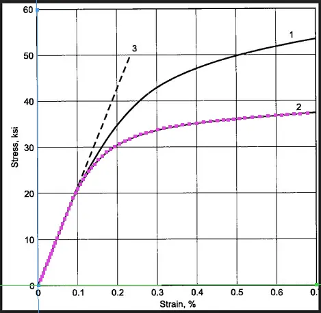
2)Data cleanup - curve fitting :- With respect to the previous step, the points on the curve 2 are evenly spaced in the same manner. If it is evenly spaced, then the chances of curve getting noisy is too low. Some of the minor fluctuations can be neglected. Hence curve fitting is not neccesary in this step. Curve fitting is done only when the data is too noisy. It is done to get the curve of best fit with more accuracy and boldness.
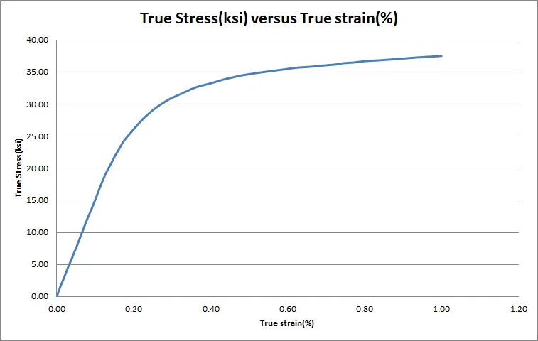
3)Data/unit conversion: True stress which is given in ksi should be converted into the true stress in GPa and the true strain which is given in % should be divided by 100. The conversion factor for converting ksi to GPa is 0.00689476
Formulas used for conversion
- True stress = Effective stress
- Effective Plastic Strain = True strain(%) - (True stress in GPa /Young's Modulus)
4) 0.2% offset yield strain: Usually for ductile materials, the behaviour of the material changes from elastic to plastic gradually, so the yield point is not well defined and cannot be detected so easily. In this case, 0.2% offset yield strength is calculated. The offset yield strength is calculated by constructing a parallel line offset by 0.002 strain to the linear stress-strain line. 0.151 GPa
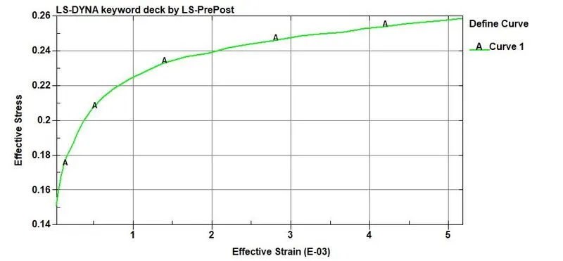
5)Defining engineering stress/strain curve for the model: The stress/strain for the material is now in the form of effective stress and effective plastic strain which can be implemented on the MAT_24 card
These data points for stress-strain curve are inserted in *DEFINE_CURVE card with LCID
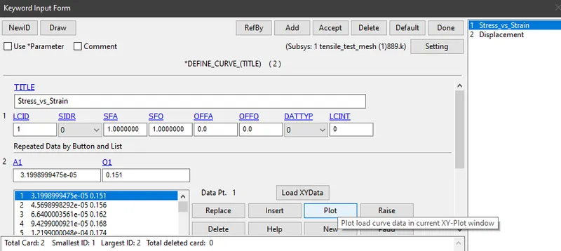
6)Performing tensile test under preprocessing: It involves importing the keyword file to LS-PrePost, creating necessary cards and apllying boundary conditions. The steps involved is explained below.
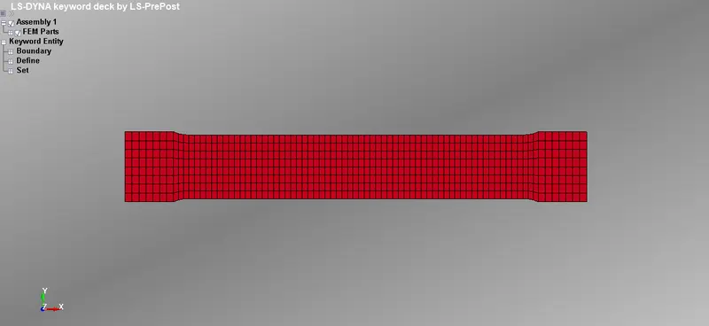
Step 1: Import the meshed keyword file of dogbone specimen to LS-PrePost
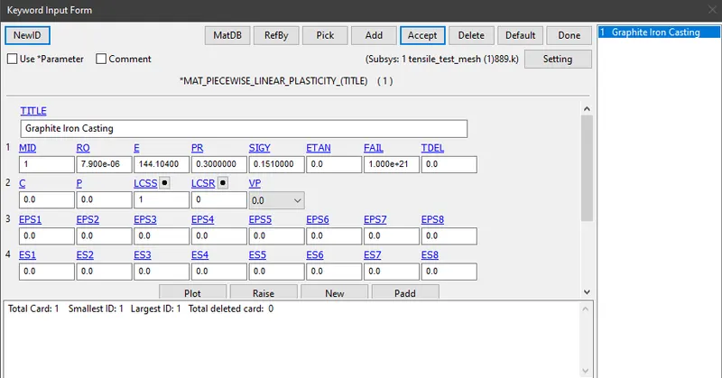
Step 2: Use the properties of graphite iron casting to define material card(MAT_24)
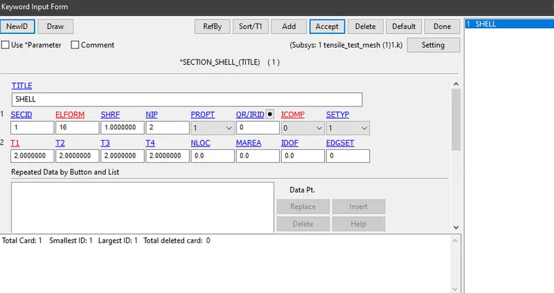
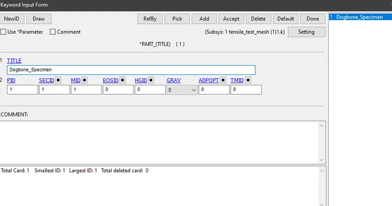
Step 3: Define the section properties for the element
Step 4: Assign the material properties and section properties to the part
Step 5: Applying boundary conditions
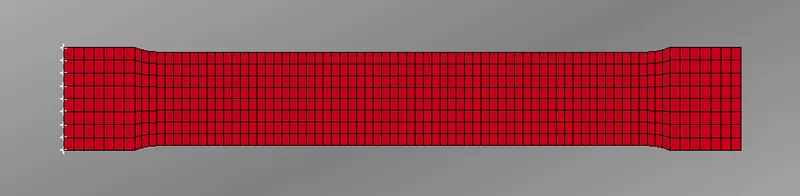
Since we are performing a tensile test where one end of the specimen is fixed and displacement is added to the other end, so two types of boundary conditions is used on the specimen
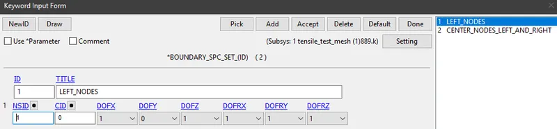
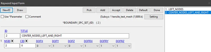
(a)Boundary SPC Set
- To fix one end of the specimen as test procedure, we will constrain all the degrees of freedom except Y-direction because specimen will elongate in X-direction and simultaneously contract in Y-direction for edge node on one end of the specimen
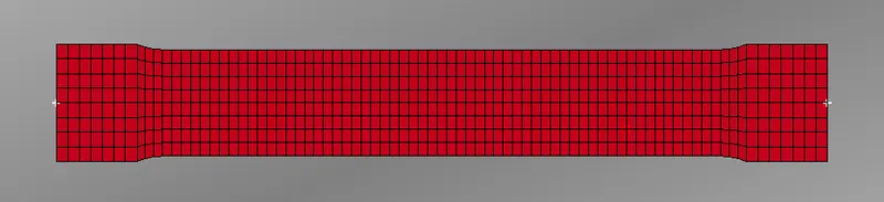
- Here, midnodes on both edge of the specimen is selected. It is constrained in all directions except X and Z
(b)Prescribed Boundary Motion
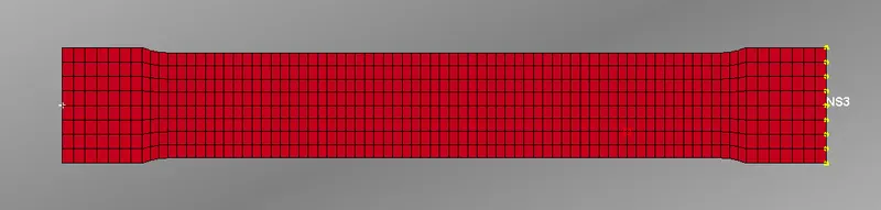
- A set of nodes is created on the right edge of the specimen where displacement is applied
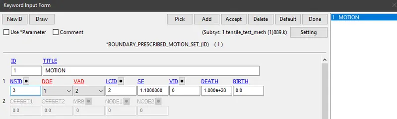
- Degree Of Freedom is set to 1 which means displacement takes place in X-direction and VAD(Velocity/Acceleration/Displacement flag) is set to 2-displacement(rigid bodies and nodes).
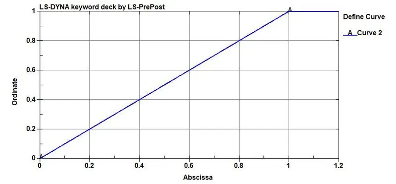
- Displacement curve is created using DEFINE_CURVE card
Step 6: Defining control cards
(i) *CONTROL_IMPLICIT_GENERAL: It activated implicit analysis and define associated control parameters. This keyword is required for all implicit analysis
- IMFLAG: Implicit/Explicit switching flag = 1
- DTO: Initial timestep for implicit analysis = 0.005
- IMFORM: Element formulation switching flag = 2(retains original element formulation)
(ii) *CONTROL_IMPLICIT_AUTO: It is defined to adjust the timestep size automatically
- IAUTO: Automatic time step control flag=1 (automatically adjust time step size)
- ITEOPT: It optimizes automatic count step = 60
- ITEWIN: Iteration window = 5
- DTMIN: Minimum allowable timestep = 0.005
- DTMAX: Maximum allowable timestep = 5
(iii)*CONTROL_IMPLICIT_SOLUTION: It is mainly used to decide whether a linear solution or non-linear solution is desired
- NSOLVER: Solution method for implicit analysis = 12(for non-linear problem)
- ILIMIT: Iteration limit between automatic stiffness reformations = 11
- MAXREF: Stiffness reformation limit per time step = 15
- DCTOL: Displacement relative convergence tolerance = 0.001
- DNORM: Displacement norm for convergence test = 2
(iv)*CONTROL_IMPLICIT_SOLVER: It performs CPU intensive stiffness matrix
- LSOLVR: Linear equation solver method = 2(It solves the simulation with single precision which constantly saves runtime)
(v)*CONTROL_TERMINATION: The end time of the simulation is specified as 1ms
Step 7: Defining the cards for database
- *DATABASE_BINARY_D3PLOT: Time interval between the outputs is given as 0.01 ms
- *DATABASE_EXTENT_BINARY: Here, STRFLG is defined as 1 to compute the elastic strain in the model
- ASCII OPTIONS: The value for GLSTAT(Global data), ELOUT(Element Output data) and MATSUM(Material Energies) is defined as 0.01
RESULTS AND DISCUSSION
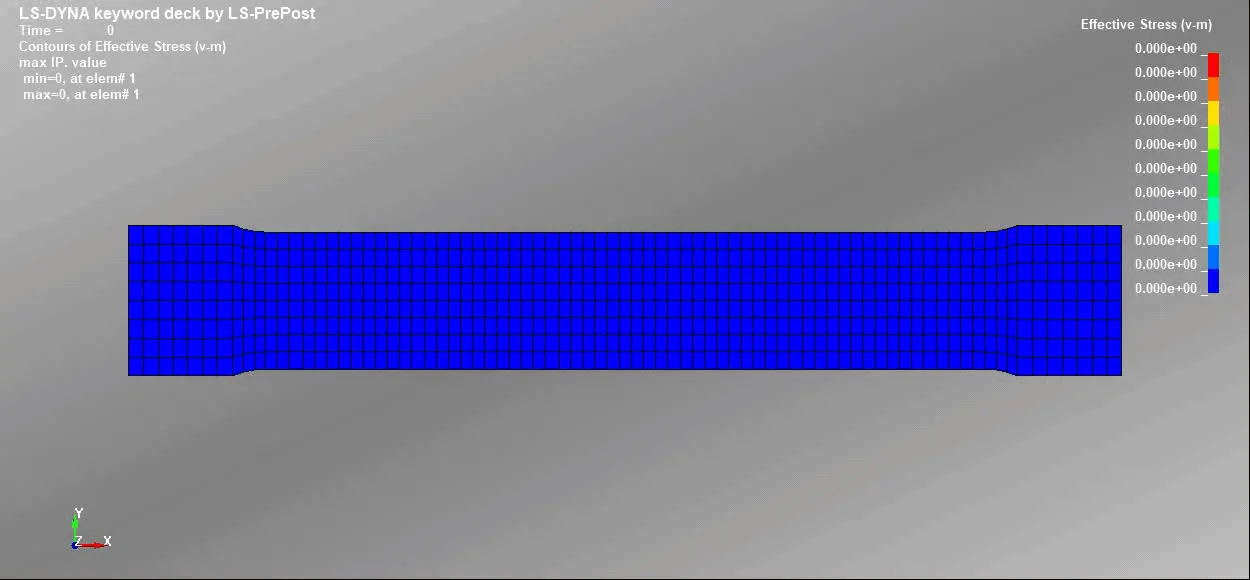
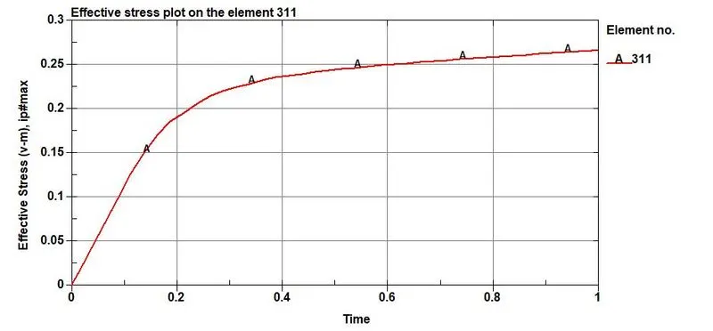
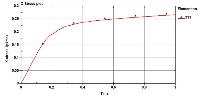
1)Von-Mises Stress: The animation of stress contour resemble the realistic simulation of tensile test. The maximum v-m stress value is 0.271185 GPa which is higher than the yield stress value of 0.151 GPa. Hence plastic deformation is occuring in the specimen. The maximum stress will occur in the middle region of the specimen
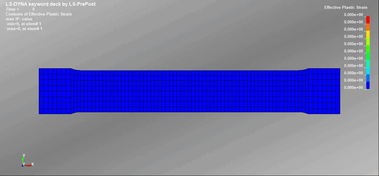
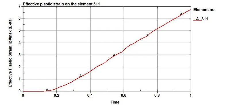
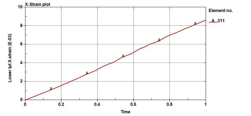
2)Effective Plastic Strain: The maximum effective plastic strain recorded is 0.00756. Due to the plastic strain, the cross-section is decreasing at the middle of specimen
3)Plot of X-Stress
4)Plot of X-Strain
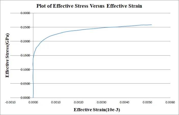
5)Plot of Effective Stress(GPa) Versus Effective Strain(%)
6)Stress-Strain values used for completing the project
| % Strain | True Strain | True Stress (ksi) | Effective Stress(GPa) | Effective Plastic Strain |
| 0.00E+00 | 0.00E+00 | 0.00E+00 | 0.00E+00 | 0.00E+00 |
| 6.06E-03 | 6.06E-05 | 1.14E+00 | 7.87E-03 | 6.00E-06 |
| 1.45E-02 | 1.45E-04 | 2.80E+00 | 1.93E-02 | 1.15E-05 |
| 2.43E-02 | 2.43E-04 | 4.88E+00 | 3.36E-02 | 9.24E-06 |
| 3.52E-02 | 3.52E-04 | 7.16E+00 | 4.93E-02 | 9.21E-06 |
| 4.73E-02 | 4.73E-04 | 1.01E+01 | 6.94E-02 | -8.34E-06 |
| 6.19E-02 | 6.19E-04 | 1.30E+01 | 8.94E-02 | -1.81E-06 |
| 7.28E-02 | 7.28E-04 | 1.51E+01 | 1.04E-01 | 3.08E-06 |
| 8.13E-02 | 8.13E-04 | 1.72E+01 | 1.19E-01 | -1.12E-05 |
| 8.98E-02 | 8.98E-04 | 1.88E+01 | 1.29E-01 | -7.94E-07 |
| 9.58E-02 | 9.58E-04 | 2.00E+01 | 1.38E-01 | 2.84E-07 |
| 1.02E-01 | 1.02E-03 | 2.10E+01 | 1.44E-01 | 1.61E-05 |
| 1.08E-01 | 1.08E-03 | 2.19E+01 | 1.51E-01 | 3.20E-05 |
| 1.13E-01 | 1.13E-03 | 2.26E+01 | 1.56E-01 | 4.57E-05 |
| 1.19E-01 | 1.19E-03 | 2.34E+01 | 1.62E-01 | 6.64E-05 |
| 1.26E-01 | 1.26E-03 | 2.44E+01 | 1.68E-01 | 9.43E-05 |
| 1.33E-01 | 1.33E-03 | 2.53E+01 | 1.74E-01 | 1.22E-04 |
| 1.42E-01 | 1.42E-03 | 2.61E+01 | 1.80E-01 | 1.67E-04 |
| 1.53E-01 | 1.53E-03 | 2.70E+01 | 1.86E-01 | 2.36E-04 |
| 1.62E-01 | 1.62E-03 | 2.79E+01 | 1.92E-01 | 2.88E-04 |
| 1.77E-01 | 1.77E-03 | 2.89E+01 | 2.00E-01 | 3.83E-04 |
| 1.92E-01 | 1.92E-03 | 3.00E+01 | 2.07E-01 | 4.90E-04 |
| 2.12E-01 | 2.12E-03 | 3.10E+01 | 2.14E-01 | 6.34E-04 |
| 2.29E-01 | 2.29E-03 | 3.17E+01 | 2.19E-01 | 7.68E-04 |
| 2.51E-01 | 2.51E-03 | 3.25E+01 | 2.24E-01 | 9.62E-04 |
| 2.77E-01 | 2.77E-03 | 3.32E+01 | 2.29E-01 | 1.18E-03 |
| 3.00E-01 | 3.00E-03 | 3.38E+01 | 2.33E-01 | 1.38E-03 |
| 3.31E-01 | 3.31E-03 | 3.43E+01 | 2.37E-01 | 1.67E-03 |
| 3.62E-01 | 3.62E-03 | 3.47E+01 | 2.39E-01 | 1.96E-03 |
| 3.89E-01 | 3.89E-03 | 3.51E+01 | 2.42E-01 | 2.21E-03 |
| 4.18E-01 | 4.18E-03 | 3.54E+01 | 2.44E-01 | 2.48E-03 |
| 4.50E-01 | 4.50E-03 | 3.57E+01 | 2.46E-01 | 2.79E-03 |
| 4.86E-01 | 4.86E-03 | 3.61E+01 | 2.49E-01 | 3.14E-03 |
| 5.10E-01 | 5.10E-03 | 3.63E+01 | 2.50E-01 | 3.37E-03 |
| 5.43E-01 | 5.43E-03 | 3.65E+01 | 2.51E-01 | 3.68E-03 |
| 5.69E-01 | 5.69E-03 | 3.67E+01 | 2.53E-01 | 3.94E-03 |
| 5.94E-01 | 5.94E-03 | 3.69E+01 | 2.54E-01 | 4.18E-03 |
| 6.25E-01 | 6.25E-03 | 3.71E+01 | 2.56E-01 | 4.47E-03 |
| 6.56E-01 | 6.56E-03 | 3.74E+01 | 2.58E-01 | 4.77E-03 |
| 6.77E-01 | 6.77E-03 | 3.75E+01 | 2.58E-01 | 4.98E-03 |
| 6.98E-01 | 6.98E-03 | 3.76E+01 | 2.59E-01 | 5.18E-03 |
CONCLUSION FROM THE PROJECT
- The stress-strain data was extracted from the given diagram using data digitizer
- The extracted stress-strain data is validated with MAT_024(Piecewise Linear Plasticity) material model
- MAT_024 material model captures the actual stress-strain behaviour in a similar manner and matched the given stress strain curve with slight variations
- Learnt to model a material from scratch and validated it using LS-PrePost