Week - 5 - Modelling Spotwelds
AIM: Spot welding is a type of resistance welding used to join sheet metals. The main objective of this problem is to model spot welds in a given assembly using beam elements and solid elements separately.
GIVEN DATA:
(i)*MAT_SPOTWELD material card should be used for both beam and solid elements.
(ii)The properties of steel are used for defining the material card.
(iii)The system of unit used here is gm/mm/ms.
DESCRIPTION: As we have created a rigid wall and given a velocity of 13.8 mm/ms in the crash box simulation, the same conditions should be given in modelling of spot welds also. Spot welds can be modelled in various manner. They are as follows
(i)By using 1-Dimensional beam elements with *CONTACT_TIED_SHELL_EDGE_TO_SURFACE
(ii)By using 3-Dimensional hexa elements with *CONTACT_SPOTWELD
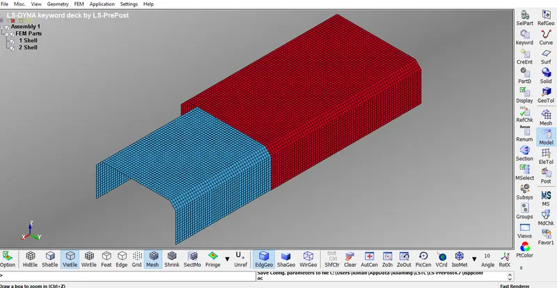
MODEL: The model on which spot welds is to be modelled is as shown below. The two sheet metals which are shown below is meshed using shell elements and they should be connected with spot welds at particular points in the model.
PROCEDURE:
METHOD 1: CREATION OF SPOTWELDS USING BEAM ELEMENTS
Step 1: Creating Spot welds at any points on the intersection
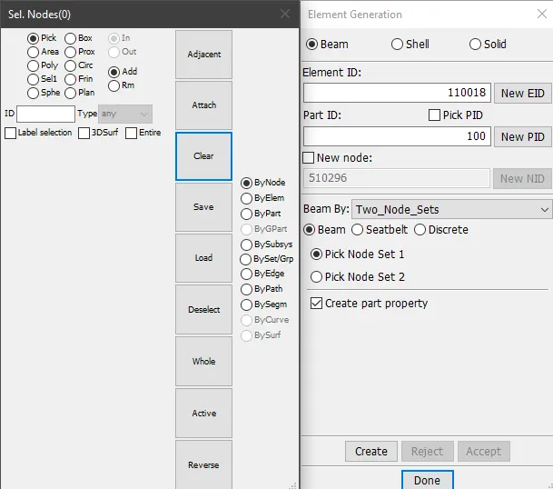
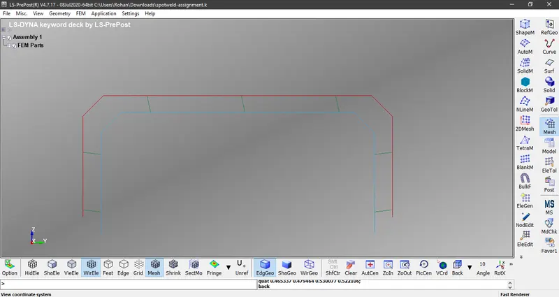
Create 7 different spot welds using beam elements at the middle of intersection of two shell elements. Here is the explanation for how it is being created. Firstly Click on Mesh on the right side of the tool bar and then choose Element Generation. Then a dialogue box will appear. Choose Beam > Part ID = 100 > Beam by = Two_Node_Sets > Pick Node Set 1 > Choose seven nodes on the shell element which is at the top > Pick Node Set 2 > Choose seven nodes on the shell element which is at the bottom > Click on Create > Accept > Done.
Step 2: Defining Material properties for the shell element
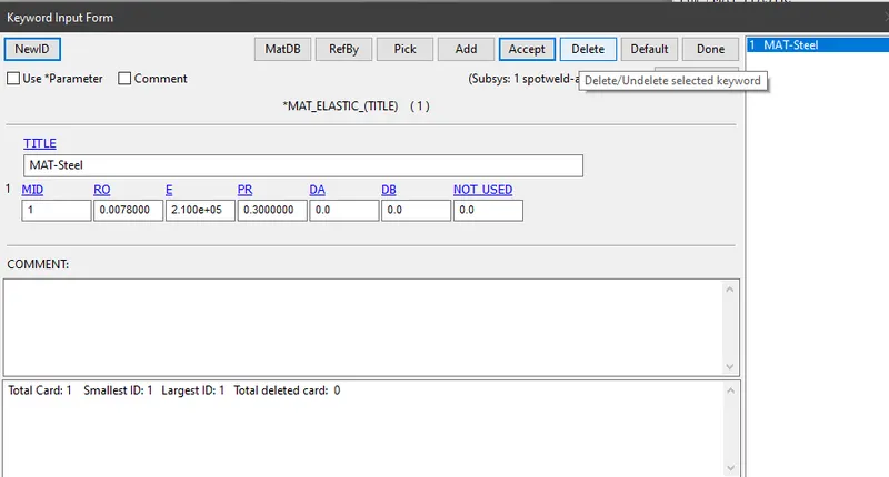
The properties of steel should be assigned for shell elements. The material card to be used here is *MAT_ELASTIC (001)
Here,
MID refers to Material Identification, A unique number should be provided in this section
RO refers to density. The value of density for steel is 0.00785 gm/mm3
E refers to Young's Modulus. The value of Young's Modulus for steel is 2.1e+05
PR refers to Poisson's ratio. The value of Poisson's ratio for steel is 0.3
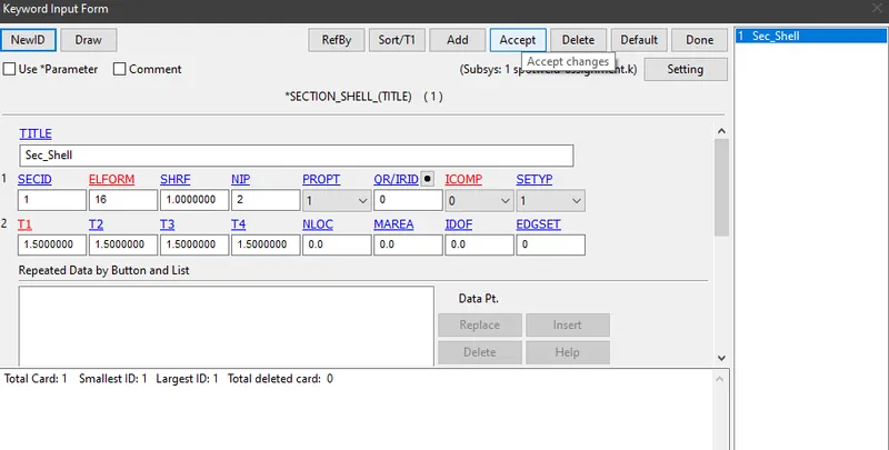
Step 3: Defining section properties of the shell elements
The sheet metals are meshed using 2-Dimensional elements, hence section has to be defined under *SECTION_SHELL. The properties for the shell elements shoule be assigned and 1.5 mm should be given as thickness for shell element.
Here,
SECID refers to Section ID, which is referenced on *PART card. A unique number should be given
ELFORM refers to Element Formulation. For fully integrated shell element, the value should be given as 16
NIP refers to Number of Integration Points = 2
SHRF refers to Shear Force Recommendation Factor = 1
T1, T2, T3 and T4 refers to thickness of the shell element
Step 4: Defining Material properties for the beam element
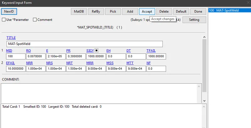
The properties of steel should be assigned for beam elements as well. The material card to be used here is *MAT_SPOTWELD (100)
Here,
MID refers to Material Identification, A unique number should be provided in this section
RO refers to density. The value of density for steel is 0.00785 gm/mm3
E refers to Young's Modulus. The value of Young's Modulus for steel is 2.1e+05 gm-mm/ms
PR refers to Poisson's ratio. The value of Poisson's ratio for steel is 0.3
SIGY refers to Initial Yield Stress
EH refers to Plastic Hardening Modulus
DT refers to Time step size for mass scaling
TFAIL refers to Failure time if nonzero
EFAIL refers to Effective plastic strain at failure
NRR refers to Axial force resultant Nrrf
NRS refers to Force resultant Nrsf or maximum shear stress
NRT refers to Force resultant NrtF at failure
MRR refers to Torsional moment resultant Mrrf at failure
MSS refers to Moment resultant MssF at failure
MTT refers to Moment resultant MttF at failure
Step 5: Defining section properties for beam element
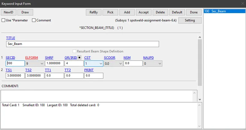
Section properties should be defined using *SECTION_BEAM. The spot weld material applies only for Element Formulation = 9 in case of a beam element and thickness of beam at both the ends is given as 3 mm. Here Cross Section Type should be selected as Tubular.
Here,
SECID refers to Section ID, which is referenced on *PART card. A unique number should be given
ELFORM refers to Element Formulation. For spot weld material, the value should be given as 9
SHRF refers to Shear Force Recommendation Factor = 1
QR/IRID refers to Quadrature rule or rule number for user defined rule for integrated beams
CST refers to Cross Section Type = 1
Step 6 : Assigning to *PART card
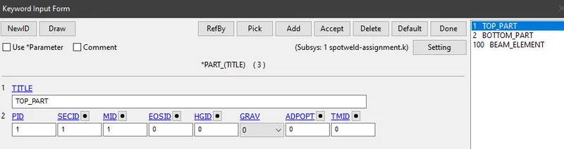
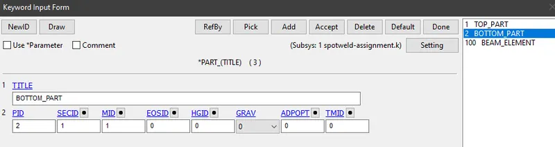
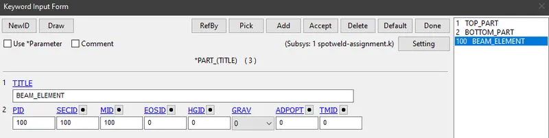
The material cards and section cards which have been defined, should be assigned to the respective parts in *PART card
Step 7: Rigid wall creation
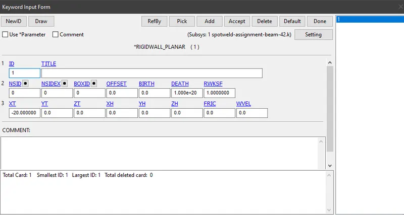
Create a rigid wall with a certain distance from the top part, so that it is going to strike the rigid wall completely
Step 8: Defining Velocity
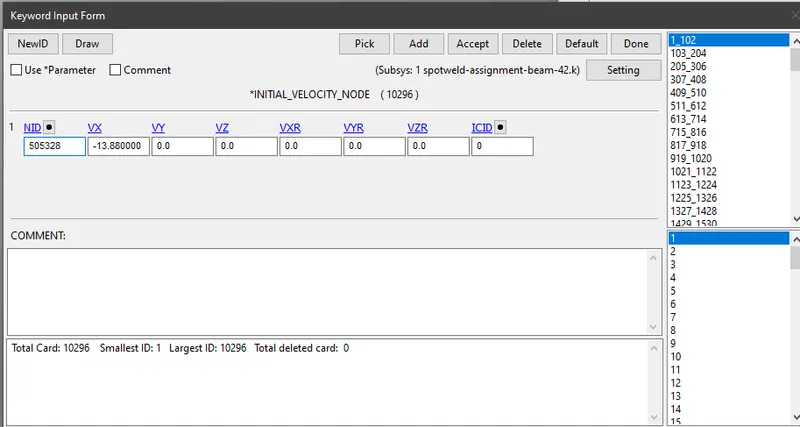
A velocity of 13.88 mm/ms is provided in X-Direction
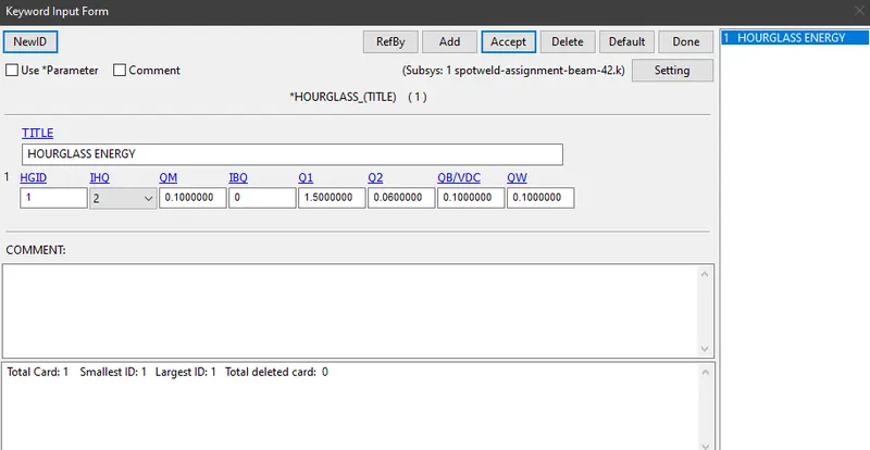
Step 9: Hourglass energy
Step 10: Control Cards
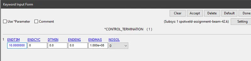
Create Control cards for Termination and Energy. *CONTROL_TERMINATION is defined as "At what time the simulation is going to end and the End time value is loaded as 10 m/s "
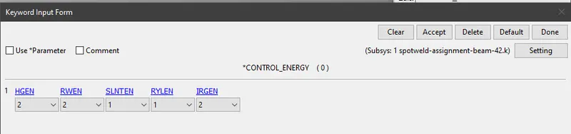
*CONTROL_ENERGY provide controls for energy dissipation options.
Step 11: Providing necessary conditions for the output files
Output files can be defined in the keyword manager. For Binary D3 Plot, select database > D3 Plot. For ASCII files, Keyword manager > Data base > ASCII. Choose elout, matsum, glstat, sleout, rcforc, rwforc, secforc, spcforc, nodout, sleout and load the values.
METHOD 2: CREATION OF SPOTWELDS USING SOLID ELEMENTS
Step 1: Creating Spot welds at any points on the intersection
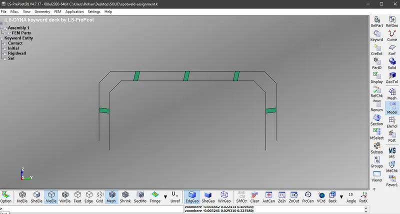
Create 5 different spot welds using solid elements at the middle of intersection of two shell elements. Here is the explanation for how it is being created. Firstly Click on Element tool on the right side of the tool bar and then choose Element Editing. Then a dialogue box will appear. Choose Elem Type = Hexa. Then select eight nodes which will form rectangular shape for each solid element at 5 different places. Here is how it will look on the front view
Step 2: Defining section properties for beam element
Section properties should be defined using *SECTION_SOLID. The spot weld material applies only for Element Formulation = 1 in case of a solid element
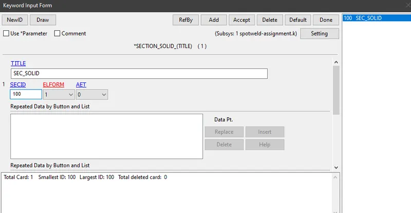
Follow the same steps as followed for beam element
NOTE: Defining material properties for solid element, defining section properties for shell element, creation of rigid wall, Initial velocity, defining hour glass energy, Control cards and output files should be given the same as given in the Beam element
LAST STEP: Run the two keyword files of beam element and solid element separately using LS-Run
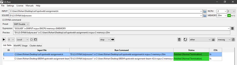
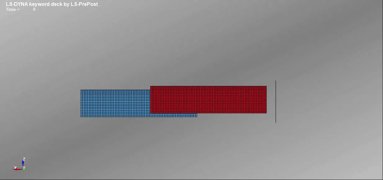
RESULT: The spot weld creation using beam elements for the given file has been modelled and the following results are obtained after simulation
1) Final Animation for beam element
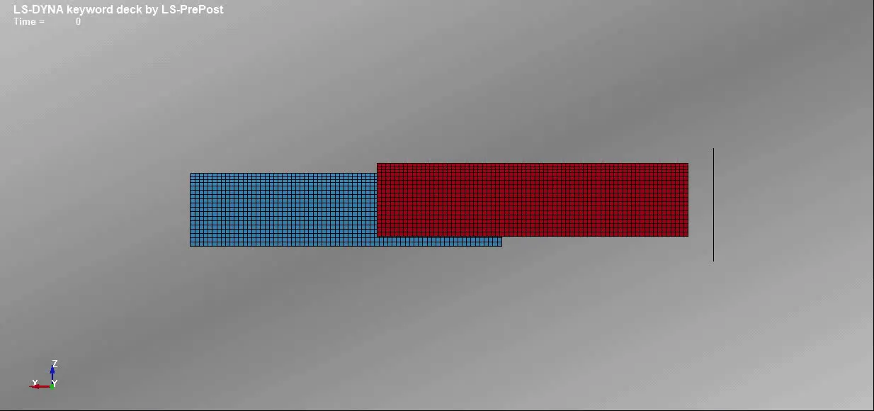
2) Final animation of Solid element
3) Plot of energies
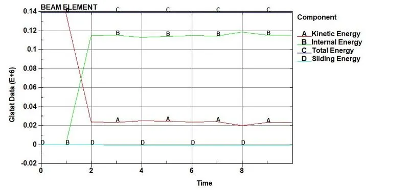
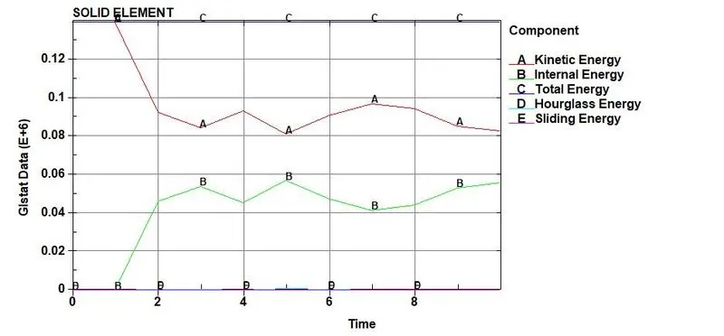
4)Plot of Hourglass energy
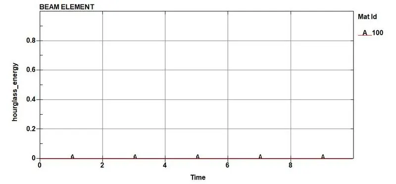
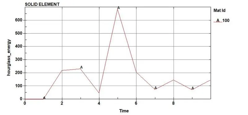
5)Acceleration plot along X-axis
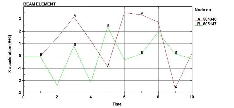
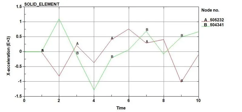
6) Axial forces acting on the element
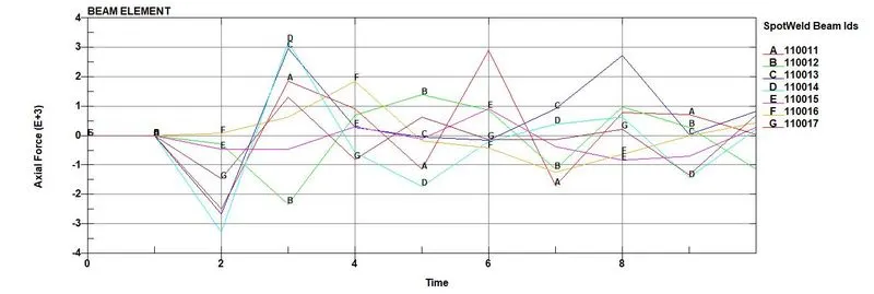
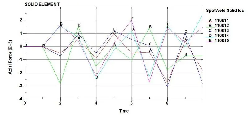
7)Shear forces acting on the element
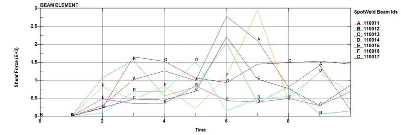
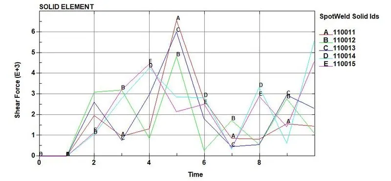
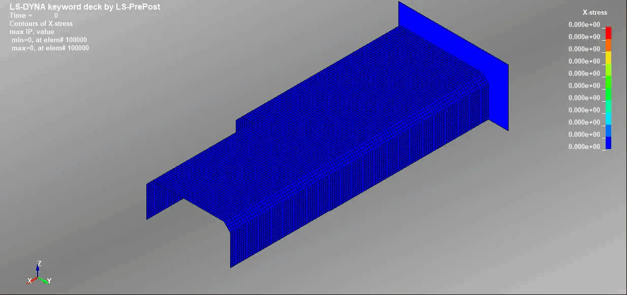
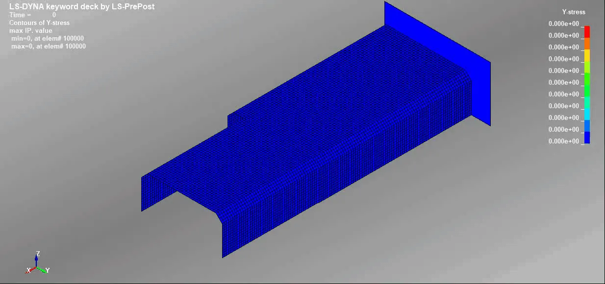
8)X Stress and Y Stress for beam element
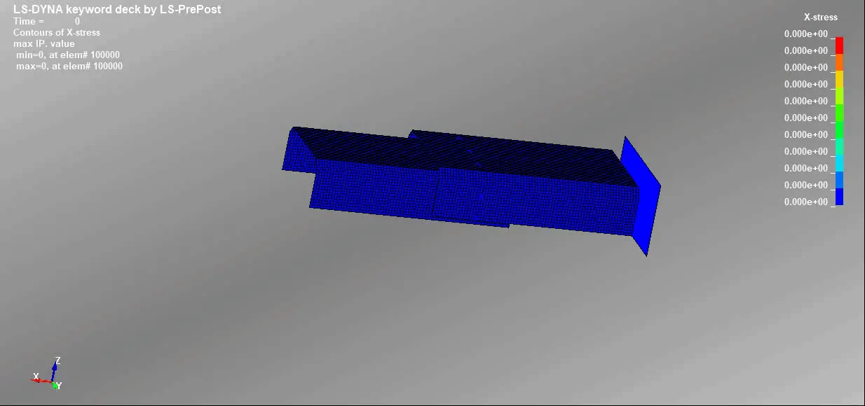
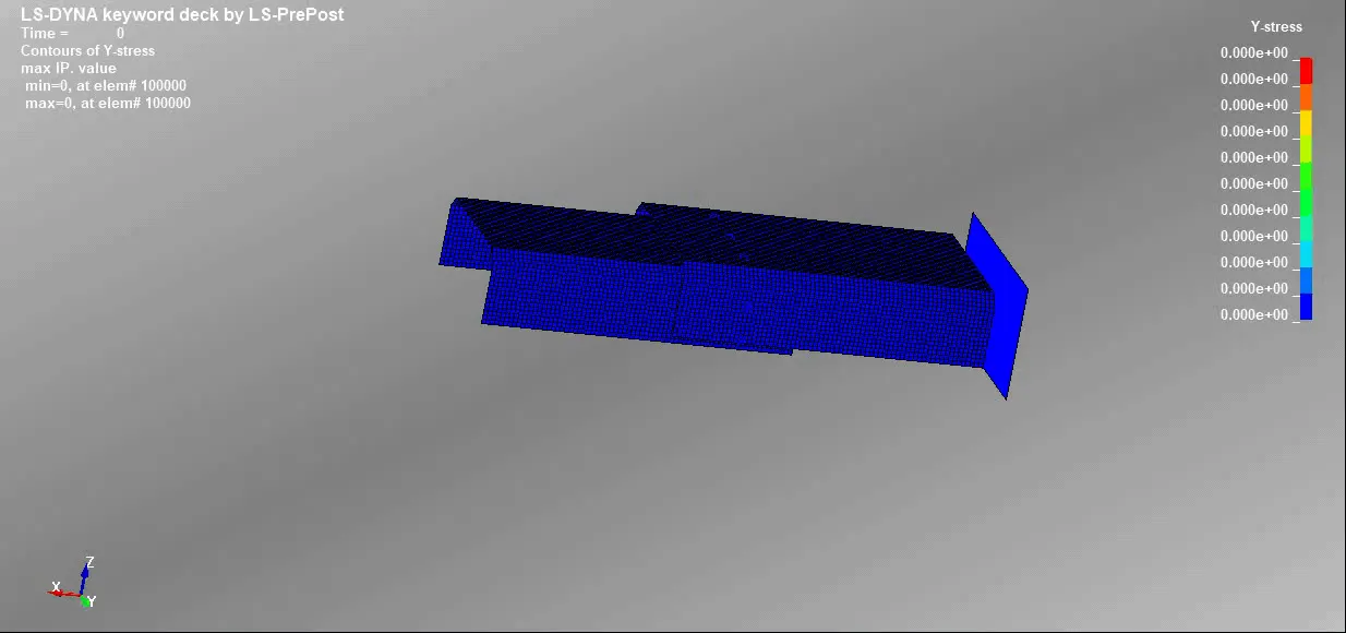
9)X Stress and Y Stress for solid element
COMPARISION:
| Description | Beam Element | Solid Element |
| Maximum Axial Force | 3.2e+03 KN | 2e+03 KN |
| Maximum Shear Force | 2.8e+03 KN | 6.5e+03 KN |
| X - Acceleration | 3.5e+03 mm/ms | 1.1e+03 mm/ms |
| X - Stress | 1669.85 MPa | 1707.07 MPa |
| Y - Stress | 1369 MPa | 1388 MPa |
CONCLUSION:
1)The spot welds are modelled using beam elements and solid elements for the given keyword file.
2)The results are plotted as shown above.
KEYWORD FILES:
For beam element: https://drive.google.com/file/d/1UsAYKpcan4845kvCT4_pOnc2RQP01n-q/view?usp=sharing
For Solid element: https://drive.google.com/file/d/1rLeRXjsLJvfLjySvPnPOdzSCft0HKIv9/view?usp=sharing