Bird Strike Simulation
https://drive.google.com/drive/folders/1OxeKUu9-sC1y4SAD2wEyeEJ9eoZy1SlI?usp=sharing
AIM:-
To stimulate non-linear transient birdstrike stimulation where the bird tries to hit the gas turbine blade by using Lsdyna.
Aircraft Engine:-
ABSTRACT:-
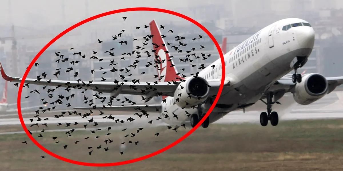
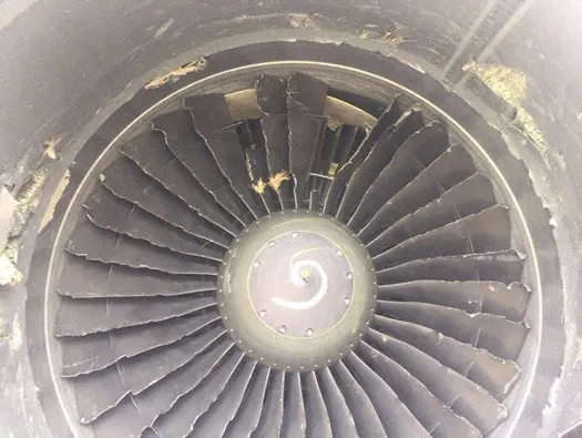
Bird Strike is common and can be a significant threat to aircraft safety. For smaller aircraft, significant damage may be caused to the aircraft structure and all aircraft, especially jet-engined ones, are vulnerable to the loss of thrust which can follow the ingestion of birds into engine air intakes
The nature of aircraft damage from bird strikes, which is significant enough to create a high risk to continued safe flight, differs according to the size of the aircraft. Small, propeller-driven aircraft are most likely to experience the hazardous effects of strikes as structural damage, such as the penetration of flight deck windscreens or damage to control surfaces or the empennage. Larger jet-engined aircraft are most likely to experience the hazardous effects of strikes as the consequences of engine ingestion. Partial or complete Loss of Control may be the secondary result of either small aircraft structural impact or large aircraft jet engine ingestion. Loss of flight instrument function can be caused by impact effects on the Pitot Static System air intakes which can cause dependent instrument readings to become Erroneous.
In some cases, especially with smaller fixed-wing aircraft and helicopters, windscreen penetration may result in injury to pilots or other persons on board and has sometimes led to the loss of control.
Although relatively rare, a higher altitude bird strike to a pressurized aircraft can cause structural damage to the aircraft hull which, in turn, can lead to rapid depressurization. A more likely cause of the difficulty is impact damage to extended landing gear assemblies in flight, which can lead to sufficient malfunction of brakes or nose gear steering systems to cause directional control problems during a subsequent landing roll. A relatively common but avoidable significant consequence of a bird strike on the take-off roll is a Rejected Take-off decision which is followed by a delayed or incomplete response and which leads to a Runway excursion off the end of the departure runway.
PROCEDURE:-
Case-1-Part creation:
1. Open The BIRD_STRIKE keyword File attached in the LS-Pre post
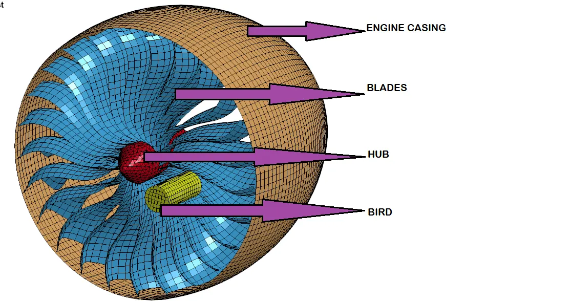
2. The Keyword Consists OF 4 Parts, Engine casing, Blades, Hub and Bird
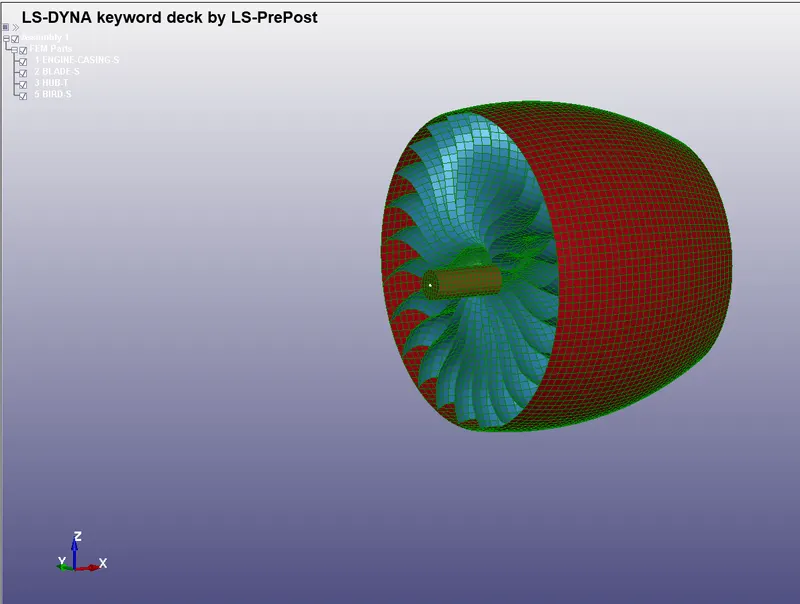
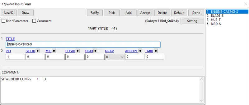
3.A new Keyword is Created Individually for each Parts eg. A new keyword is created for Hub and a keyword for Blades Which Consists Only PART in it.
1-HUB 2-Blades
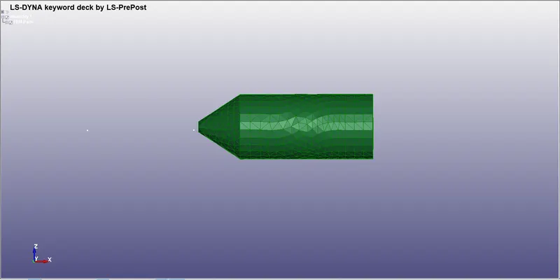
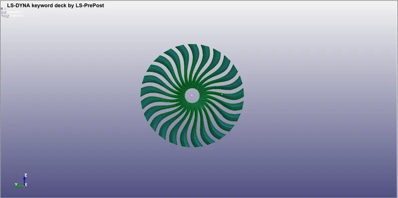
3.-BIRD 4- Engine Casing
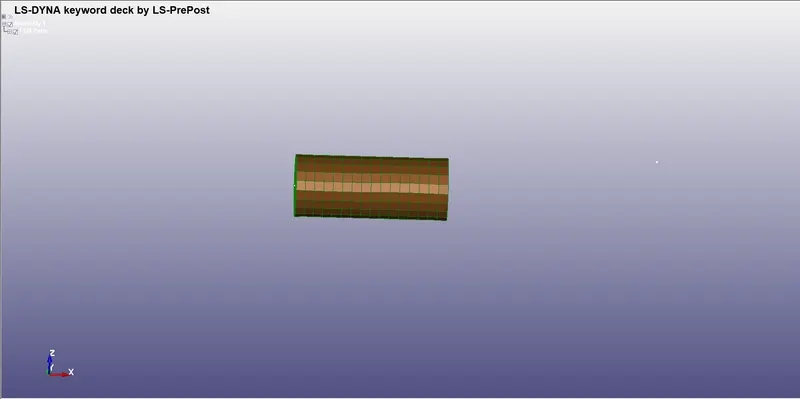
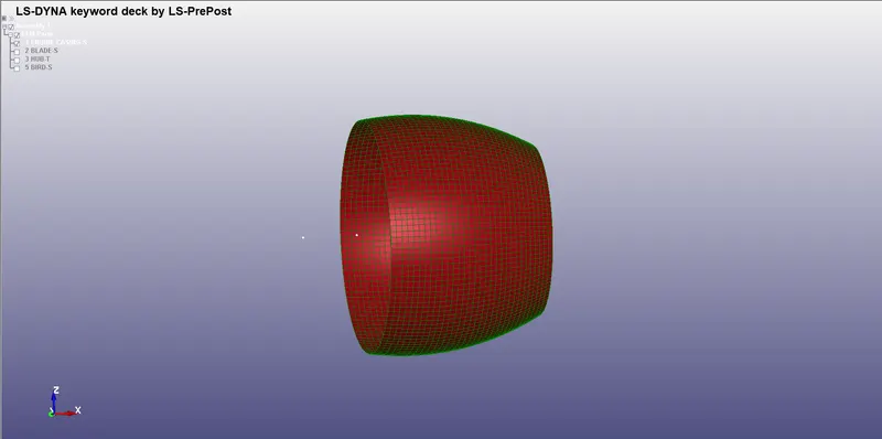
4.An separate keyword is created for these parts
Case-2-Material and Section creation:
Birds Material:-
1. MAterial and Section Is created For assigning to the Parts Created with the Unit system KG, mm, ms
2. An new Keyword File Is opened In LS Pre-post which is mainly for Section And Material
3. For The Bird The Material Properties Are Taken From Research Paper
4. As the Bird is Soft material a density of 2.0e-06 kg/mm^3Given
5. Young's Modulus Of the Bird is Given as (2000MPa) 2 GPA and Poisson's Ratio as 0.47
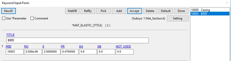
Engine Casing:-
1.For Engine Casing Mat Elastic card is Assigned with Properties Of Steel
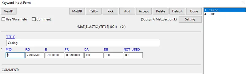
Engine Blades:-
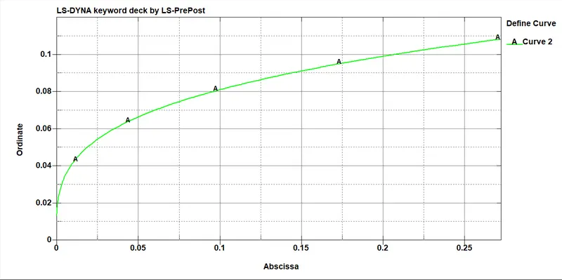
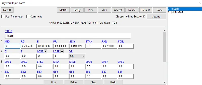
For Blades, MAT_024_Peicewise Linear_plasticity Is assigned with Properties Of Aluminium9945, and Load Curve Is assigned for The Plastic Strain behavior
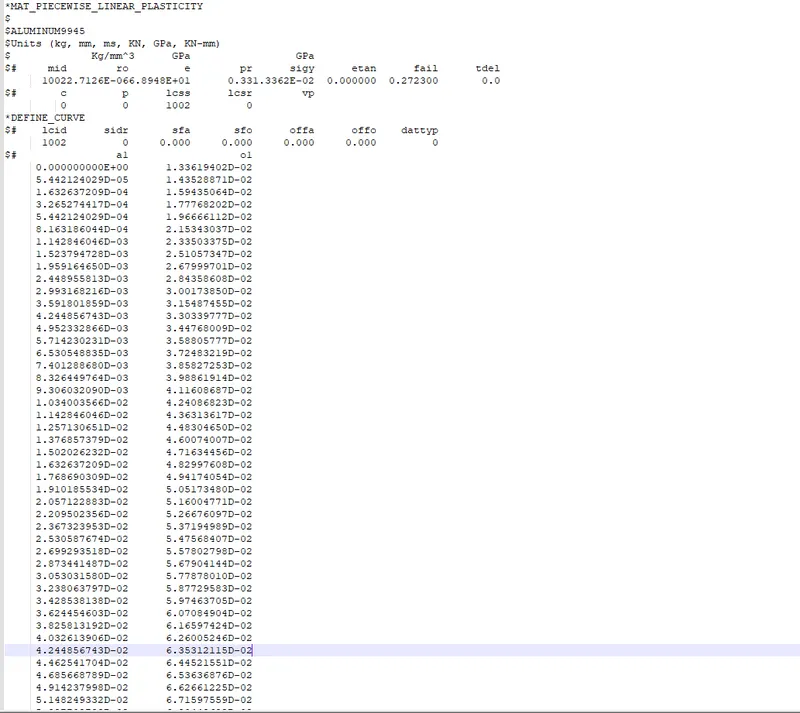
HUB:-
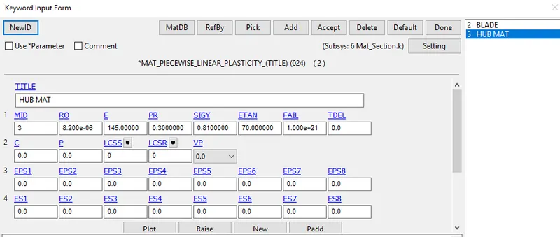
For The Hub Same MAT_024_Peicewise Linear_plasticity is assigned with the Properties of steel
Section Creation:-
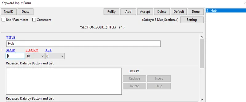
1. As the Hub is Modelled with the Solid Elements *SECTION_SOLID card is Assigned with ELFORM=10
2.The Engine Casing, bird, blades are Modelled with the Shell Elements, So *SECTION_SHELL card is Assigned with Respective Thickness of each and with Suitable ELFORM
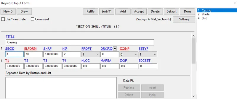
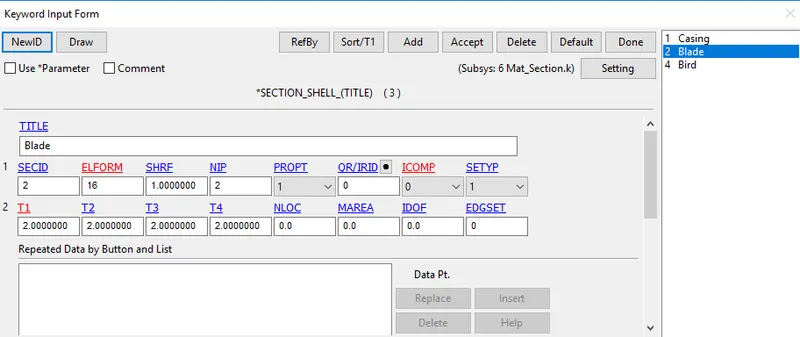
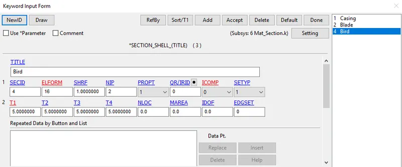
3.The Keyword file is Saved as Section and Material individually
The Part Keywords and The MAterial and Section Keywords are Included into Single Keyword Using *include > Include Option
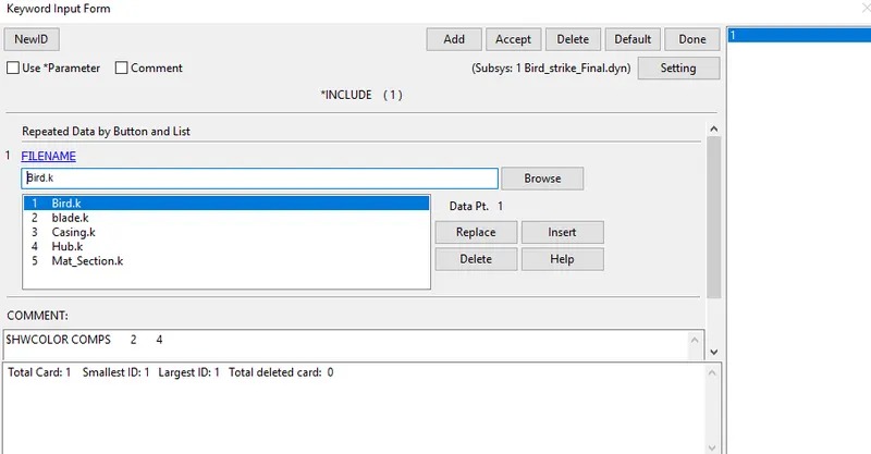
The Include File Is saved as Bird_strike_Final with .dyn extension for Easy access the New keyword Consists of Parts with the respective Section and material assigned according to the ID given
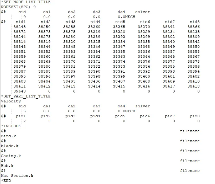
CONTACT CREATION:-
The part that Coincides with another part Is defined as Sets so the Contact is created In the Main file for easy Acess
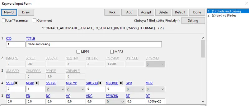
1.The Project deals with the Bird striking on the Engine Blade, so a contact AUTOMATIC_SURFACE_TO_SURFACE contact is Assigned as Birds as Slave and the Blades as Master
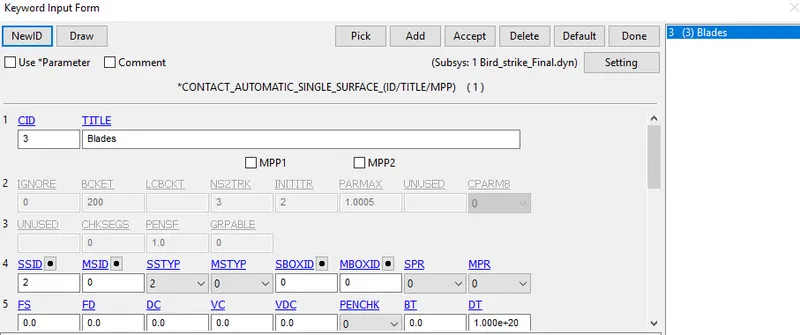
2. After the Impact there is a wide chance of Blades getting Broken and collide with each Other, For that Case, AUTOMATIC_SINGLE_SURFACE is Assigned considering blades As Slave and Master
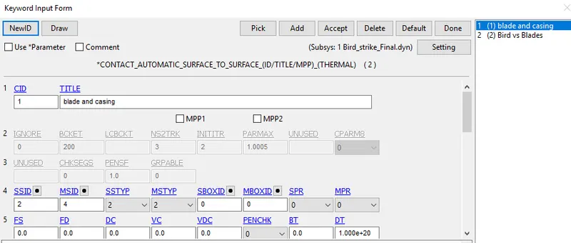
3.During The case of impact The blades Might get broken and Chances of hitting the case, so for this case, AUTOMATIC_SURFACE_TO_SURFACE contact is Assigned as Casing as Master and the Blades as Slave
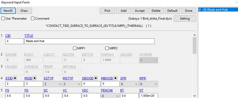
4.As the Hub is Modelled with Solid Elements and the Blades are Modelled with Shell Elements Its Tied To each other With The TIED_SURFACE_TO_SURFACE contact as Hub as master and Blades as Slave
BOUNDARY CONDITIONS:-
INITIAL VELOCITY:-
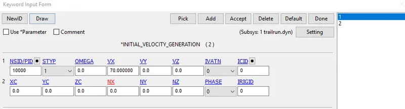
1. The Average Velocity in which Bird Travels is Taken from The Outside Sources and It's Found to be Approximately from 20 to 80 mm/ms which may vary according to the weight Of the Bird
2. As the Weight of the Bird Here is around 9.126e-06 kg which is very less so The Minimum Velocity is Assigned to the Bird as 70 mm/ms Along X-axis
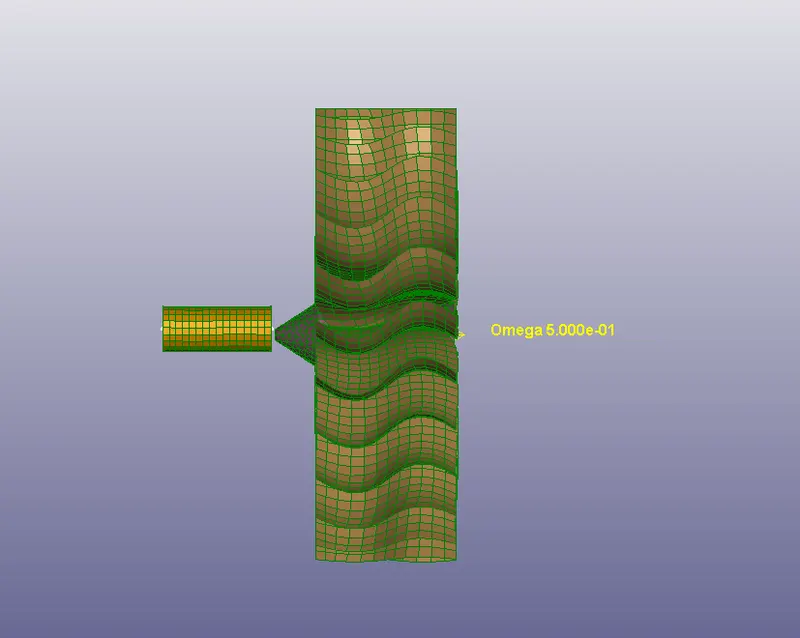
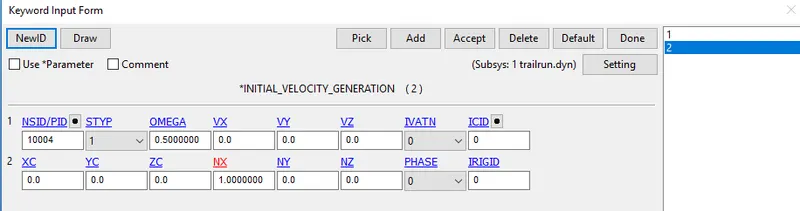
3.For the Blades and Hub Angular Velocity Must be Defined
4.The Average Speed of an Aircraft turbine Is around 3000 to 20000 Rpm
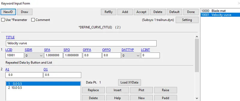
5.The Rpm is Considered as 5000 here which is 0.5 rad/ms
6.The Angular Velocity is Given as 0.2 rad/ms In this case along X direction Cosine
SPC:-
1. The Casing IS constrained In all Axis Of DOF as it should remain Unmoved During the time of Impact
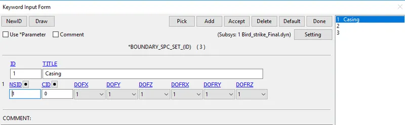
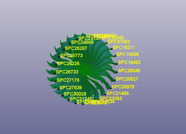
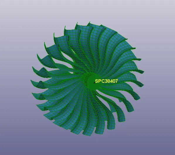
2.The Blades and the Hub should be Unmoved at the time of Impact so the Corners of the Blades and Centre point of the Hub are Constrained in X-axis
Boundary Prescribed Motion SET
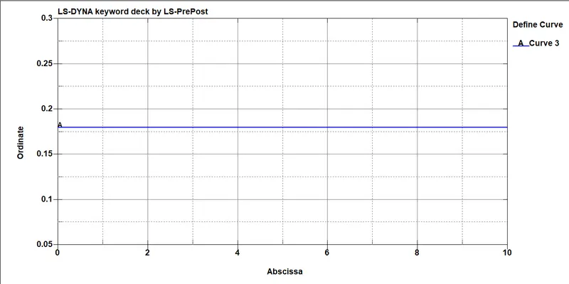
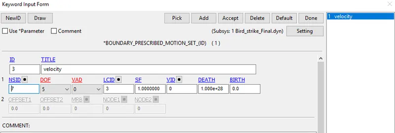
1.At the Time of Bird Impacting on the Blades, the velocity of the Blades might get Reduced, WHich is against the Real-time scenario so Prescribed Motion is assigned to the Hub and the Blade to maintain a Constant Velocity Throughout the Simulation
Renumbering IDs:
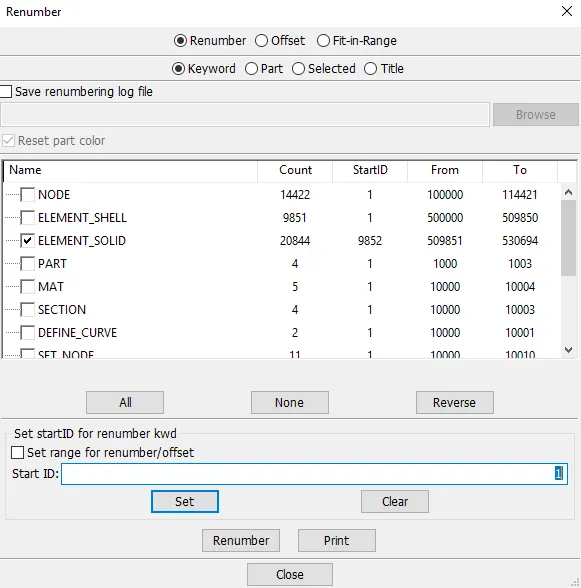
Each part of the model setup is opened in LS-Prepost individually and their node, element, and part IDs are renumbered accordingly in such a way that 100000+ for nodes, 500000+ for elements, and 1000+ for the parts. This method follows a consistent numbering approach which is used commonly in industries that deal with complex projects.
CONTROL CARDS:
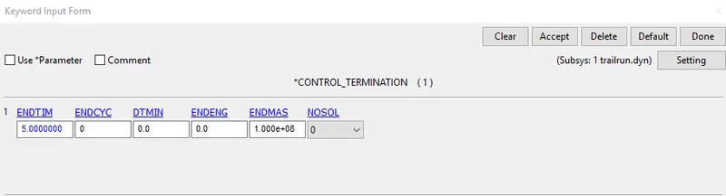
1.Run time of the Simulation is set to 10ms using *CONTROL_TERMINATION card
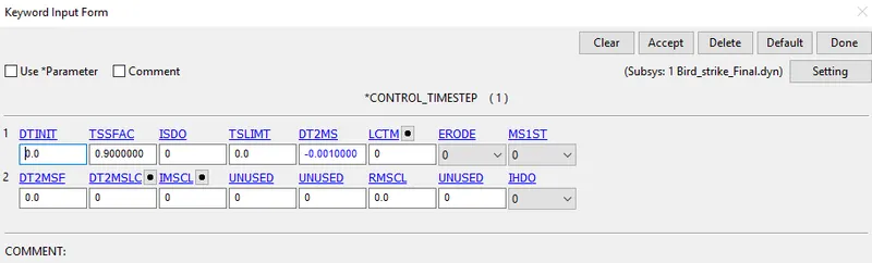
2.For Performing the Simulation Faster Control Time Step card is Assigned with a random mass scaling value
OUTPUT REQUESTS:-
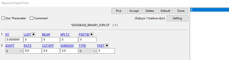
1. BINARY_D3PLOT - It defines the frequency at which the animation file is to be created and is set to 0.05ms
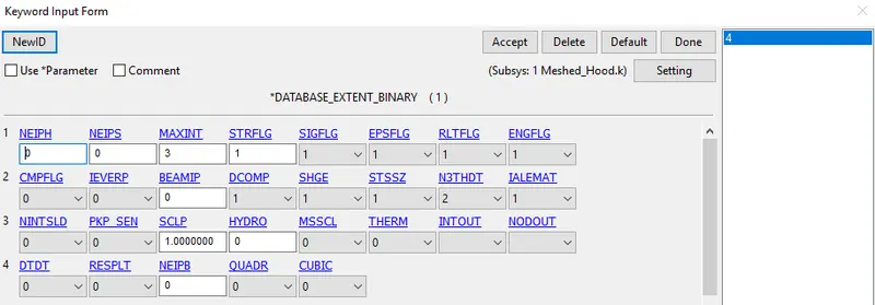
2.DATABASE_EXTENT_BINARY- This is used to write Strain Tensor data To the D3Plot when STRFLG is set to 1
3. Go to Keyword Manager > Database > ASCII select GLSTAT, RCFORC with DT 0.5
4. ELOUT, MATSUM, GLSTAT, RCFORC, RWFORC, SWFORC, NOD OUT this required option assigned into the ASCII option.
Results:-
1.Check the Model using Model checker For any errors and save the Keyword
2. Run the Simulation using LS Dyna manager and check the D3 plot for animation
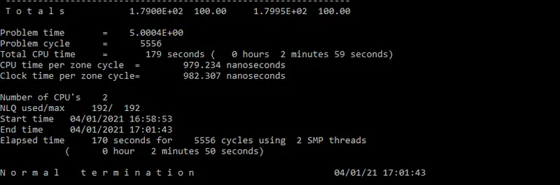
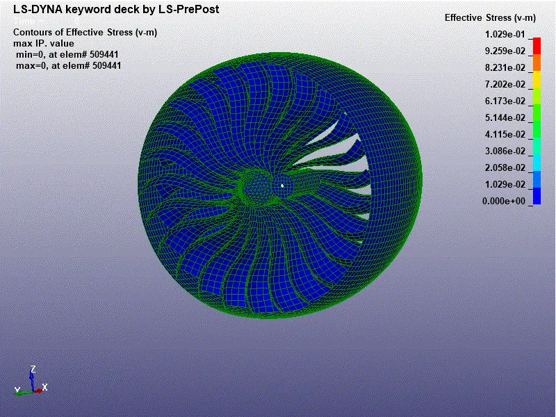
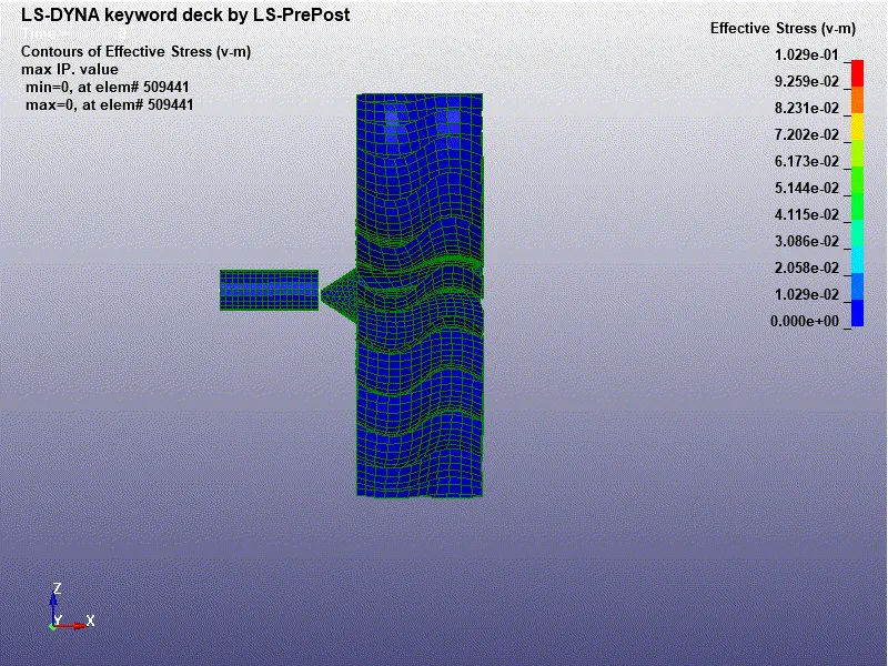
As the Thickness of the Bird is Given as 5mm and the Thickness of the Blade is 2mm It is seen that the Bird hitting the Blade and it's getting broken due to the Impact of the Bird velocity
Due to the Imposed velocity Given the Blade Doesn't stop after impacting
Due to the Centrifugal force, The Bird initially Pulled Slightly Inwards And Moved away later
The Maximum Stress Acted During the Impact Is 0.102Gpa At element 508655
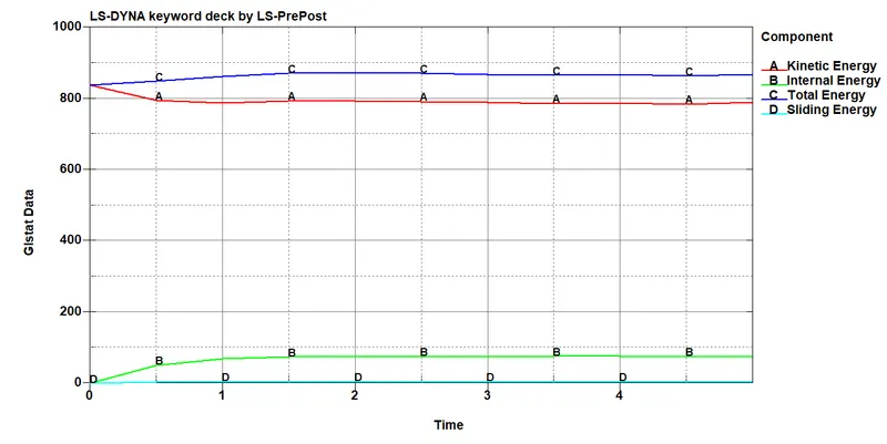
From The Graph, we can see that The Bird Impacts Which Is in the form of Kinetic Energy, The Blade Deforms
Correspondingly the Internal Energy Of the System Starts Acting In the Opposite Direction To the Kinetic energy
So the Plots Satisfies the law of Conservation Of Energy
As the Result, The Total energy of the System Remains In linear Mode Throughout The Impact
Component-1003-BIrd:
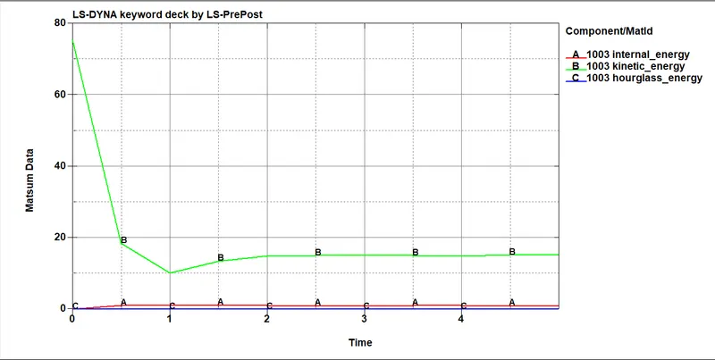
From the Graph, The Kinetic energy Of the Bird is Decreasing At the Time Of Impact and Remains Constant After 2ms
As the Bird is Less in Size and MAss The Internal energy Produced By the Bird is Very less
Component-1001-Blades:-
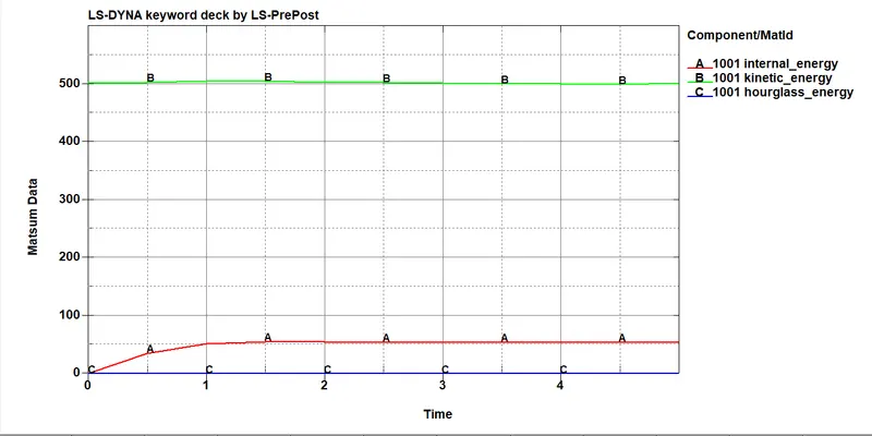
From the Graph, the Kinetic energy of the Blade remains Constant because of the Imposed Velocity Given To it
The Internal energy Produced By the Blades are Sufficient to Its Properties and Comparitiveley Acceptable With the Internal energy of the Bird
Contact Energies:-
The Contact AUTOMATIC_SURFACE_TO_SURFACE is used between the Blades and Bird considering Blades as Master And Birds as Slave
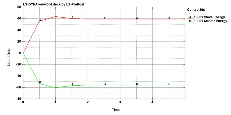
From the Graph, the Energies Produced by the Same Are equally Distributed
Inference:-
1.In the Simulation Bird Is Assigned with Elastic Material and With general Properties, Thus the results Obtained FromThe Simulation Can not be Compared with the Realtime Data
2.Generally The Bird Is Modelled With Smooth Particle Hydrodynamics (SPH), which Replicates The Simulation Similar to the real Bird
3.FromThe Simulation Its Evident that The COmputational Methodology can be Used For Certification, as it Consumes Less cost and Time Compared with Physical Testing
4.From LS Dyna Different Types Of Bird Model Can be Used and the Results Can be Compared with the Original data
5. For Getting Exact Replicate of Original data Different Computational Methods Using Lagrangian, Eulerian, Linear Polynomial and EOS Can be Used along with SPH
6.The Material Properties Might Vary According to the Blades used By different organizations and It can be Solved And results Can be Compared.
CONCLUSION:-
Finally, The Simple Bird Strike on the Aircraft, Simulation was Carried Out Using LS Dyna And Its results Are Plotted.