Assignment 7-Side Pole Crash Simulation Challenge
Title: Side Pole Crash Analysis of BIW of Vehicle using Hypermesh and Hypercrash
Aim: To setup the side pole crash analysis for RADIOSS solver using Hypermesh and Hypercrash based on the industry standards.
Objective:
Following are the objectives of the analysis,
- To check and follow the consistent unit system.
- To create the appropriate interface, with 0.2 friction and recommended parameters.
- To check for the penetration, intersections in the model.
- Correct all possible errors in the model.
- To create a rigid wall(cylindrical) with friction 0.1.
- To compare the model weight with the fuu scale 300k nodes model and adding the masses of the missing component using the Add Mass option.
Abstract:
An automobile car body structure is designed in such a way that the major loads are carried by the strcture. In case of accidents the design of the structure should be such that the safety of the passenger is highest priority. In these view various safety standards are introduced since long time. Various standards are set from region to region. The actual testing requires time and is expensive. Hence using the computational power available with current advance technologies FEA analysis comes into the picture.
A crash simulation is a virtual recreation of a destructive crash test of a vehicle using a computer simulation in order to examine the level of safety of the vehicle and its occupants. The information obtained from the analysis indicates the capability of the structure and required modifications to improve the structure.
Requirements for the side pole crash test:
Following are some of the side pole crash test standards that are followed.
Diameter of the Pole = 254 mm
Velocity of the vehicle = 8.611 m/s
Run time = 80 ms
Time Step = 0.1 to 0.5 microsecond
Time Frequency for the Output = 0.5ms
Procedure:
a. Consistent Unit System.
It is of high importance to follow the consistent unit system to prevent the false results from the analysis. A small error in maintaining the unit system may lead to false results, which are of no use. Hence it is of high importance to follow same unit system. In this work kg-mm-ms unit system is used over entire analysis definition.
In order to check the unit system the starter input file is checked. The file with the format [simulation_name]_0000.rad is the starter input file. This file has all the model data including nodes, boundary condition, velocity, etc. On the other side the file with ending 0001.rad is known as the engine input file. This file contains all the information about the simulation. For e.g run time, time step, number of animation files, number of time history files, etc. It can be controlled using the engine cards.
The starter input file is used to check the unit system. Following image shows the representation of the starter input file in Notepad.
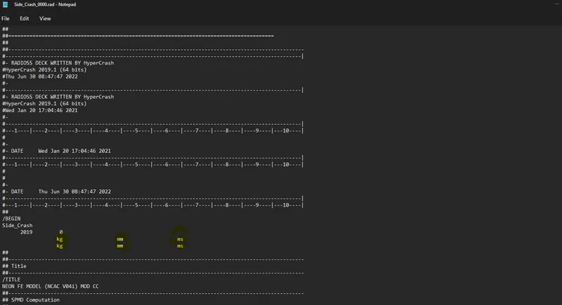
It can be seen that the unit system deployed in the simulation is kg-mm-ms.
In this work the simulation setup is done using the Hypercrash software.
The given model is imported in the Hypercrash. Following is the screenshot of the Hypercrash software with the mesh model of the BIW.
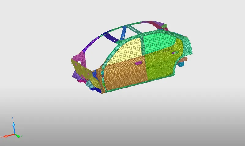
Due to the limitation of the node limit for the student license. The simplified model is used, the missing components are taken into consideration using the rigid body and the added masses. It is important to make sure that the center of gravity of the vehicle is positioned at the same position as that of the simplified model.
b. Check for penetration and Intersection
It is of high importance to check for the intersection and penetrations. As due to presence of this there could be issues like lowering of the time step of the simulation affecting the computation time. To check the penetration and intersection go to , Quality > Check Intersection on Tree > Select the parts > Check on penetration
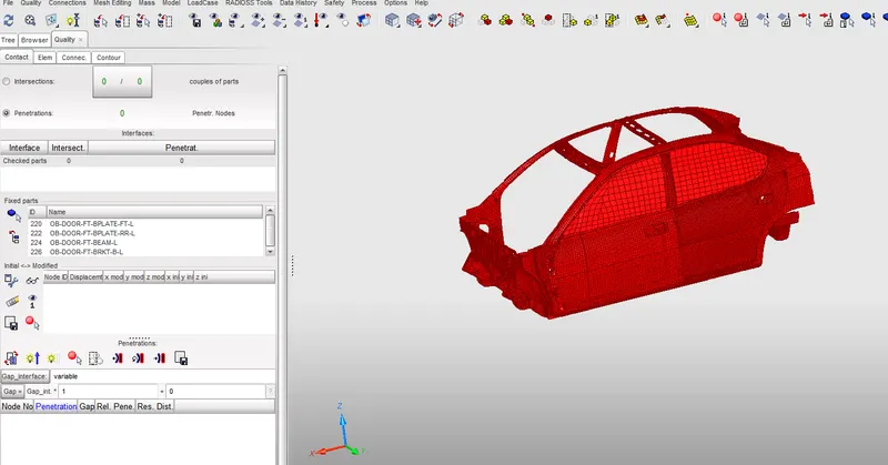
It is clear that the model does not have any penetrations and intersections.
c. Vehicle Weight and CG
Vehicles Center of gravity is the point where the sum of all the masses of the components act. The position of the CG is of high importance as it predicts the behaviour of the structure after the crash. Hence as the model used is a simplified model, it is important to have the CG of the simplified model at the same position as that of the Entire vehicle model (i.e 300k nodes).
In order to consider the missing components, in this work the mass is added to the components using rigid body. For eg figure below shows the consideration of the engine components and its mass at the position added with the mass using Add mass option. The mass is added to the node using Type 1 add mass option.
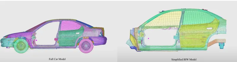
In the above figure it can be seen that after matching the weight of the missing components the CG of the simplified BIW is at same position as that of the complete vehicle model.
d. Contacts/ Interfaces
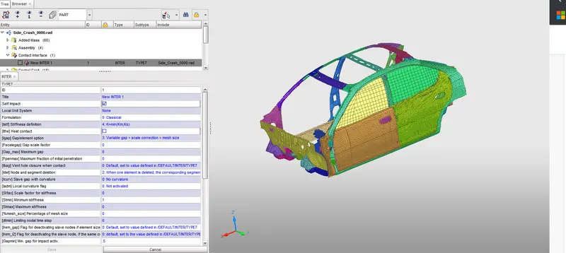
In this work the Type 7 contact interface is defined. Interface TYPE7 is a multi usage impact interface, modeling contact between master surface and a group of slave nodes. It is also possible to consider heat transfer and friction in this type. All the limitations of Type 3,4 and 5 are solved with 7. The only limitation is the non consideration of edge to edge contact, hence it is used with Type11.
Following are the recommended properties for the contact interfaces
Igap = 3 (Variable Gap taken into account)
Gapmin > 0.5 mm (Minimum thickness to avoid the numerical issue.)
Inacti = 6 (remove initial penetrations wherever possible)
Istf = 4 (Stiffness based on softer segment)
Stmin = 1 kN/mm (Minimum stiffness in contact to avoid too soft contact)
Idel = 2 (Remove slave nodes from contact due to element deletion)
Iform = 2 (Frictional forces are calculated on the basis of stiffness parameter)
e. Rigid Wall
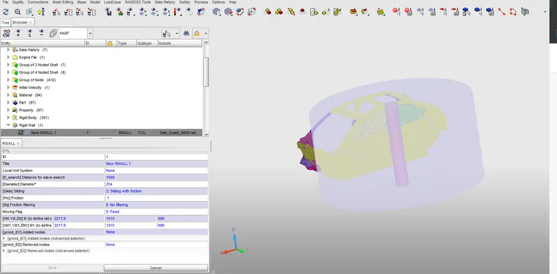
For side pole crash the pole is created using cylindrical rigid wall option available. The BIW is impacted on the pole. A cylindrical rigid wall with diameter of 254 mm. The position of the rigid wall is at the B Pillar region. The search distance is 1500 mm.
Following are the parameters of the Rigid Wall
Friction type = 2 (Sliding with friction)
Frictional Coefficient (Fric) = 0.1
D- search distance = 1500
Master Surface = Entire Vehicle
f. Initial Velocity
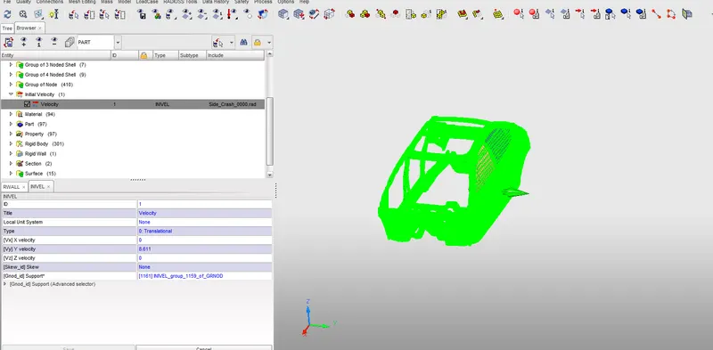
The vehicle is impacting on the rigid pole with initial velocity of 32 mph (8.611 m/s). This is given using the initial velocity option available in the hypercrash loadcase.
g. Sections
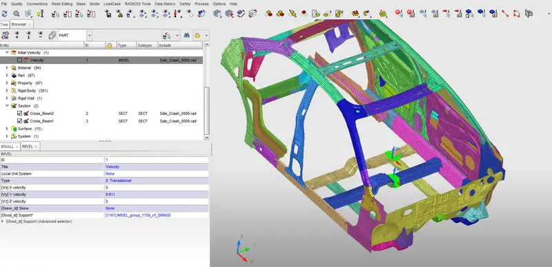
The output of the analysis is to analyse the sectional forces in the driver and B pillar rail in the BIW. As in the side crash the vehicle is crushed in the side part the cross members experience high forces and for most of the industrial analysis the crashworthiness of the cross member is interested to validate whether they are structurally strong enough and crashworthy enough in case of the crash. Hence in this work, sections are created in the cross members and normal force in the sections are recorded.
Following figure shows the sections created in the cross members
h. Intrutions at the B Pillar region
As the BIW is impacting on the pole, the B pillar and the door of the car are experiencing high deformations, it is important to evaluate the intrutions in this region as the passenger and driver are present in this region. Usually the regions are defined in the test to define the intrutions, in this work certain nodes are defined with a frame of reference and the displacement is tracked with respect to this frame.
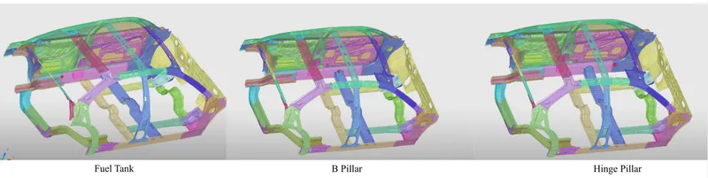
The figure above shows the location of the nodes for evaluating the intrutions. These nodes are activated in the Time History with the variables such as the displacement, etc with respect to the frame. The alternative way to evaluate the information is using the springs with very low mass and stiffness and request the elongation of the springs.
Apart from this another output request is to evaluate the peak velocity in the door region. This is activated in the Time History section.
Hence TH node is used to request displacement, peak velocity of the nodes of interest. Apart from nodes TH inter is used to evaluate the forces in the interface and TH section for the sections to record the sectional normal forces with the frame created.
i. Control Cards
It is important to use the necessary control cards to run the simulation. These are saved in the engine file which define the simulation.
- Time Step Control: Based on the type of the element the time step control method is defined with its corresponding Tmin.
- Engine Run: The total termination time of the analysis is defined in this control card.
- ANIM_DT: The frequency of the animation output files to be printed.
- TH: This card is used to print the time history data with its data points at certain time interval.
- ANIM_Mass: This card is used to animate the mass of the model, in case of addition of extra mass for time step control can be visualised using this card.
These are some of the cards used in the analysis.
After following above process it is important to check the model for the errors before submitting it to the solver. The Model Checker is used to check the errors and warnings in the model. It provides all the possible errors such as incompatible boundary condition, model definition,etc.
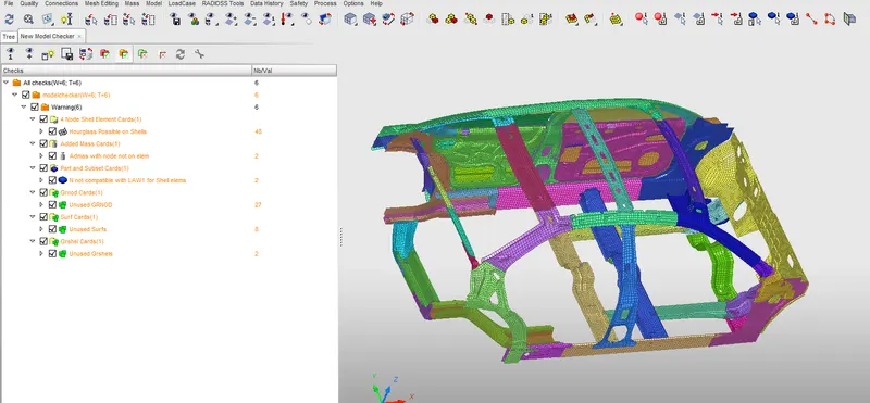
As it can be seen there are no errors rather few warnings which can be avoided.
The next step is to submit the input file to the solver. The file is imported in the Hypermesh and is submitted with the RADIOSS profile to the solver with -nt 8 option.
Post Processing:
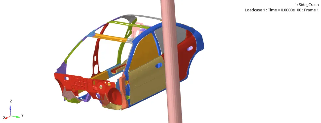
After the analysis is completed with the normal termination and no any errors, the .h3d file is opened to see the visual inspection of the analysis, if there are any flying components or any missing joints, etc. Following animation shows that the crash visually looks right as the intended crash is occcuring with car is impacting on the pole. The .h3d file is opened in Hyperview
Von Misses Contour
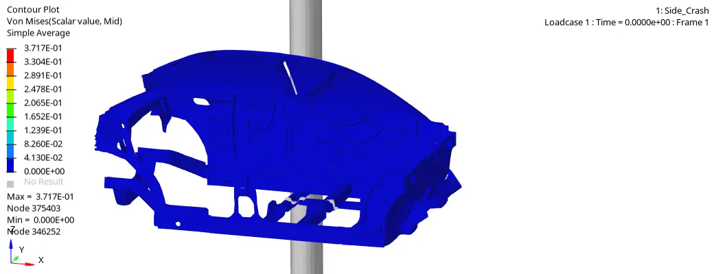
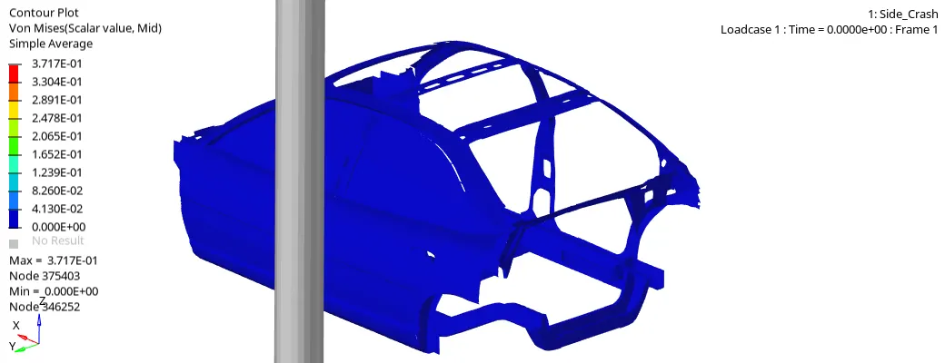
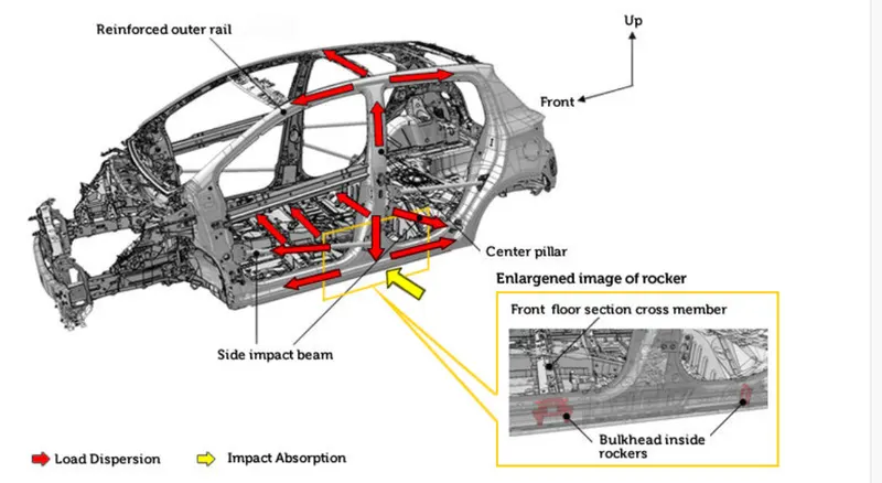
It can be seen from the above contour plots, the BIW is impacting on the R-wall cylinder with a velocity of 8.61 m/s, initially the B-Pillar gets in contact and later the forces are transfered to the left and right direction in the roof rail and cross member in the bottom as shown in figure below. In each step the forces are decreasing due to the absorption of energy.
Assessment of the simulation:
Energy and Mass Error:
While solving the model in each step the energy and mass exchange happens in the system. Mass is added into the system to control the time step and energy is added or lost from the system due to contact and friction or hourglass. It is important to have conservation of energy and mass in the system.
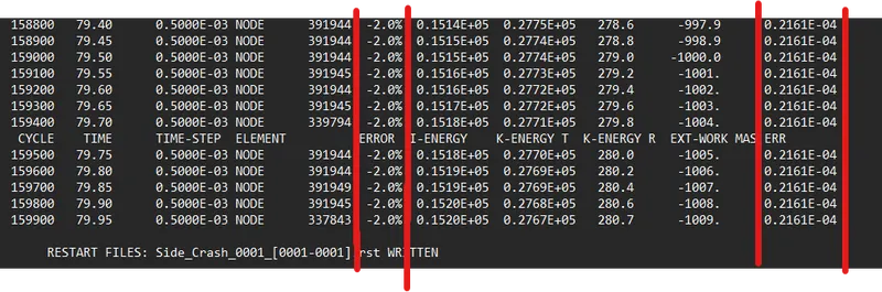
It can be seen that energy error is around -2% and mass error is almost 0%. These values are way below than acceptable values. This concludes that the results from this analysis are correct and can be used for the assessment.
Global Energy Plot
In Hypergraph 2D the kinetic, internal and Total energy is plotted to see the conservation of energies. Following plot shows the energies in the system.
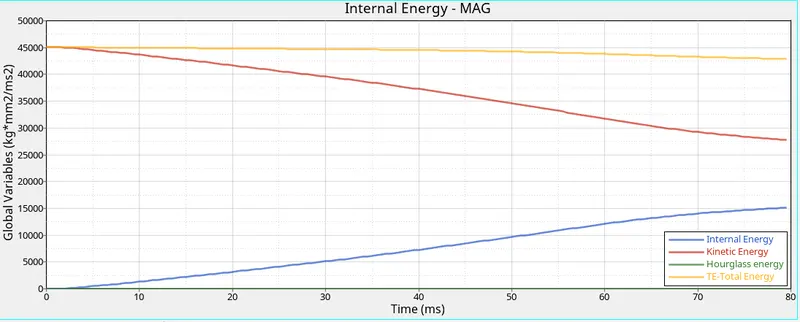
It can be seen that the Total Energy of the system is almost constant over entire analysis. The Kinetic energy at the beginning of the simulation is high whereas the internal energy is zero, with the time the Kinetic energy is converted into the internal energy. The Hourglass energy is almost zero due to the QEPH elements used in the analysis.
Peak Velocity Plot: One of the objective of the analysis is to evaluate the peak velocity in the door region. While setting the analysis the Time History of the node was requested with velocity as the variable. Following graph shows the velocity with respect to time.
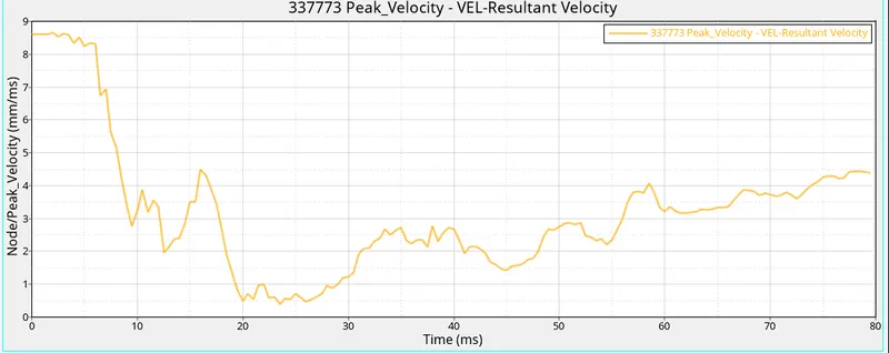
The peak velocity at the door is around 9 m/s. As when the BIW hits the pole the first contact occurs near the door region and due to the crushing the inner portion of the door might hit the passenger inside the cat and lead to injuries.
Intrustions in the requested regions.
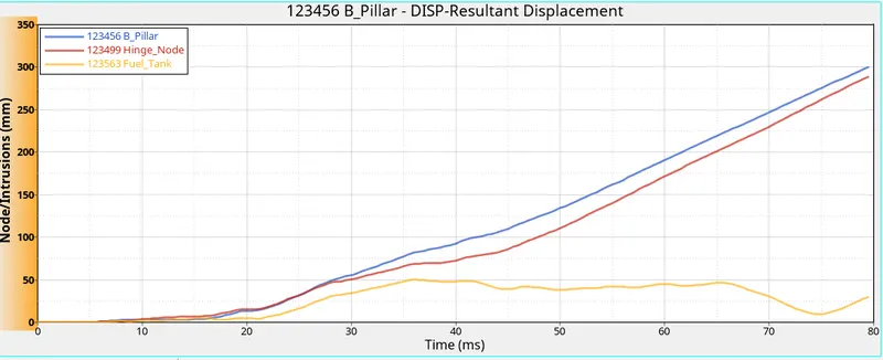
The graph above shows the intrutions in Fuel Tank, B Pillar and Hinge Pillar node. The intrutions in the Fuel tank are very low around 50mm whereas the intrutions in the B Pillar and Hinge Pillar are around 300 mm. In order to reduce the intrutions cross member stiffness can be increased so that the deformations are less and the safety is increased.
Sectional Forces.
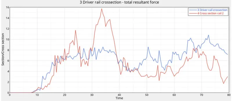
The cross members are the parts that transfer the force from one side to another absorbing the energy and stiff enough to resist the force such that the intrutions are less in the passenger compartment to prevent the injuries. It can be seen that initially the B pillar is in contact with the pole, due to this force acting on the cross members is rising once the cross members crumble the value of the force is reducing due to buckling and bending of the cross members.
Learning Outcomes:
Following are the outcomes from this work;
- How to setup the side pole crash analysis
- Creating R Wall, Sections, Springs, etc
- Force vs Displacement of the interested nodes
- Post Processing of the results, understanding the mechanics and necessary actions required.
Conclusion
The given model was simulated for the side pole crash using RADIOSS profile and results were obtained. The validation of the analysis was done using the Energy and Mass error. The intrutions in the passenger cabin are below the acceptable region. In order to reduce the intrutions in the fuel tank region cross members can be introduced. Due to the limitation of student license a specifir recommendation cannot be made.