Week - 5 - Modelling Spotwelds
Title : Modelling of Spot Weld using Beam and Solid Element in LS Dyna
Objective: The main objective of the simulation is to understand the difference between the modelling of the spot welds in LS Dyna
Following are the objectives of the simulation,
- Model spot weld using beam and solid element.
- Compare axial and shear force in both the cases.
- Crash analysis of the welded parts.
Procedure:
- Pre-processing:
The given mesh file is first imported in the LS Pre Post. Following figure shows the mesh,
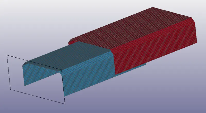
The two plates are welded together at the half region the number of spot welds is kept to 7 such that the symmetry is achieved. In first case the welds are created using beam element and second case the welds are created using solid elements.
a. Beam Element spot weld
The first step is the beam element generation. The beam elements are created using element generation option in Element and Mesh tool.
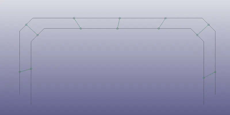
Figure above shows the beam elements created between two plates. All the nodes of the beam element ends are added to a node set.
The node set is created using the Creat Entity option.
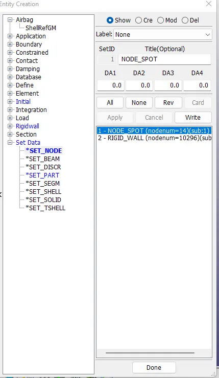
Next the Plates are added to a Part Set. This makes the contact definition an easy task. The contact between the beam elements and the plates is tide edge to surface type.
Materials
a. Beam Element
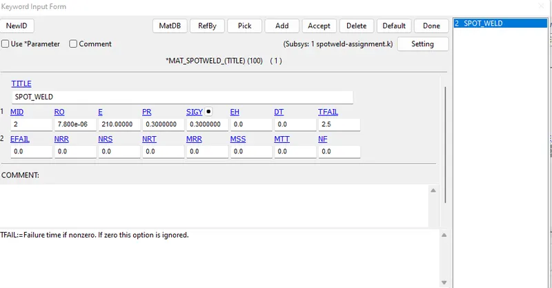
As the beam element represent the spot weld, the MAT_SPOTWELD (MAT100) is used as the material for the beam elements with the property of steel material. Initially the failure of the beam elements is given such that the beam elements fail at the half termination time. Following is the card for the spot weld material.
b. Plates
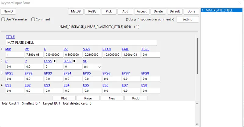
The material for the plates is steel. The material card used for the plates is PIECEWISE_LINEAR_PLASTICITY (MAT24).
Section Card
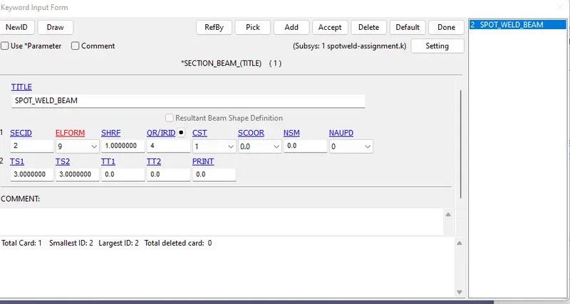
a. Beam Element: As the material used is MAT SPOT WELD. The element formation for the beam element is kept to type 9
b. Plates
The element formulation for the steel plates is 16
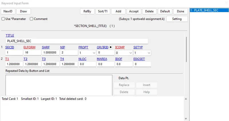
The thickness of the shell plate is 1.2 mm and the number of integeration points is 2.
Contact Definition:
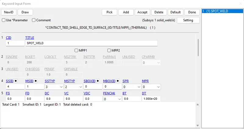
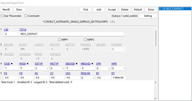
The contact between the spot welds and the plates need to be defined. The plates are always set to master and the spot welds as the slave side. In this the contact used is Contact Tied Shell Edge to Surface type. The master side is selected using Part set and the slave as the node set, defined in the previous step. Following card shows the contact card for the analysis. Apart from this the self contact is also defined using the Automatic Single Surface for both the plates set to as slave side. This contact is given because in case the spot weld fails and the two plates come in contact with each other and this should not lead to instability.
Boundary Condition:
Initial Velocity:
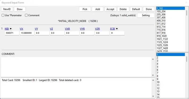
The plates are crashing on a planar rigid wall created from the create entities option. The model has the initial velocity of 13.88 mm/ms. The initial velocity is given from create entity option. The velocity is given to all the nodes.
Control Card
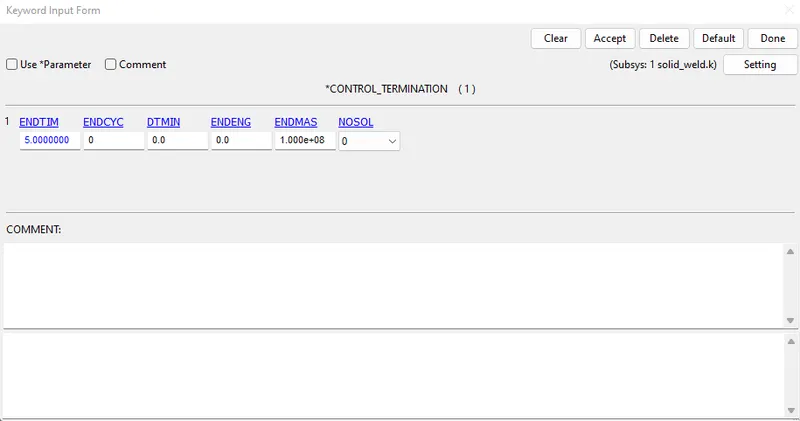
Termination: The analysis time is set to 5ms. Control Termination card is used for this, the end time is set to 5ms.
Database Card
Binary D3Plot
Binary D3plot is printed with DT value of 0.1 ms. ASCII outputs such as global energies, SWFORC, NODOUT, is requested to get the spot weld forces and moments, nodal displacement and veolcity respectively. The NODOUT card doesnt works unless DATABASE_HISTORY_NODE is activated. So this is defined first.
After setting up this, the model check is performed to check for any errors and warnings and the model is ran in LS Run.
b. Spot Weld Using Solid Elements:
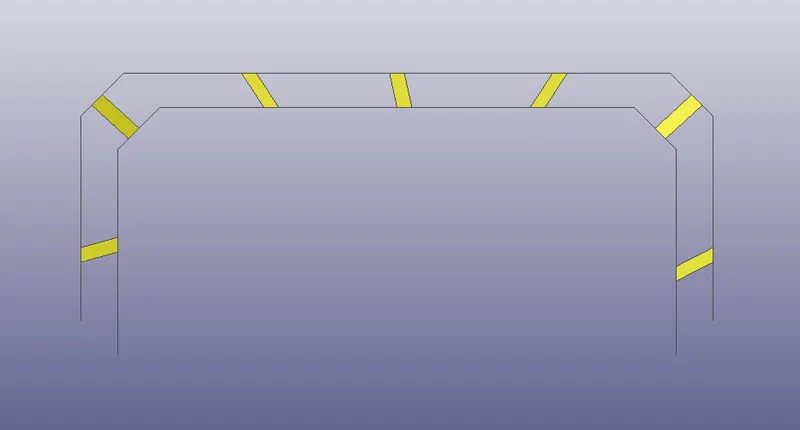
In this case the spot welds are created using the solid Hex elements. The procedure almost similar to the beam element setup as discussed earlier. The only difference here is the Beam Element is replaced by the solid element. Following figure shows the solid elements created as the spot welds which later are added to a part set.
Material for the Solid Spot welds:
The material is same as that of the one used for the beam elements, i.e MAT100 (MAT_SPOTWELD). The material properties of steel are given and the time failure is used for the failing of the spot welds such that the welds fail at half of the termination time.
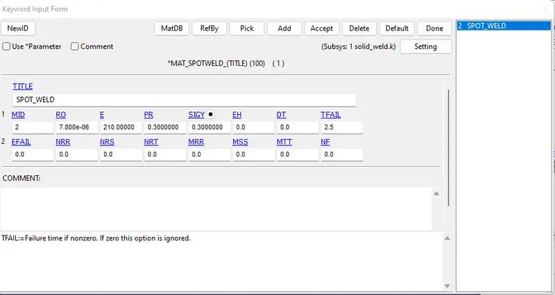
The material for the plates is not changed.
Section Card
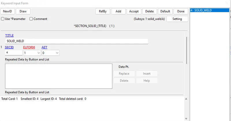
The section is changed in this case, as the solid element is used instead of the beam elements. The solid elements are used with element formation type 1. It is mentioned in the LS Dyna manual that the spot weld should be used with the element formulation 1.
Contact Definition
The Contact type here used is the Contact Spotweld. The master part is set as the plates and the solid spot weld elements are set as the slave part. The Plates are added into a Part Set which is referred later.
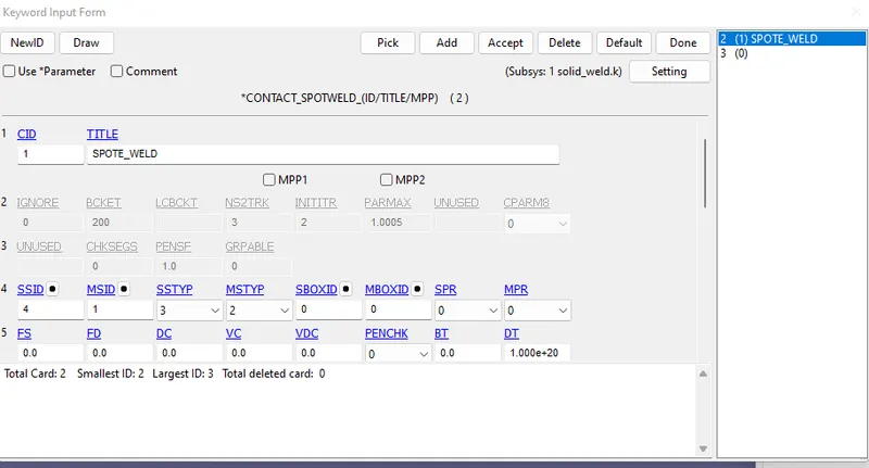
Rest Boundary Conditions, Control Cards, Database Card, etc remains unchanged as the earlier run.
Post Processing:
Case 1: Spot weld as Beam Element
The plot below shows the axial forces generated in the beam elements. The maximum force is around 1.8kN
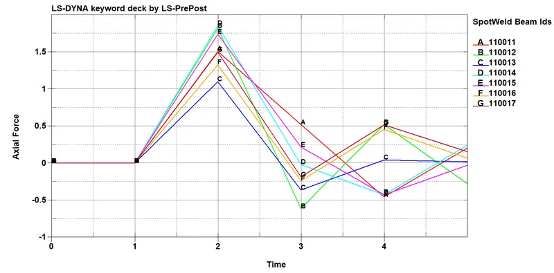
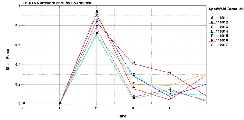
The beam diameter is 2mm and hence the cross section area is 12.56 mm sq. Theortically the max tensile stress is Force divided by area, which gives 1800/12.56 around 143 MPa. This value is lower than the tensile yield strength of steel material used for the spot welds. Similalry following plot shows the shear force which results into shear stress value of 73 MPa which is also below than shear yield strength of material (150 MPa i.e 0.6*Sys)
Case 2: Spot weld as solid elements
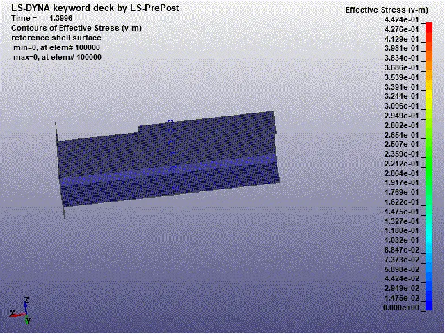
Visual Animation of the analysis with the effective stresses (von misses)
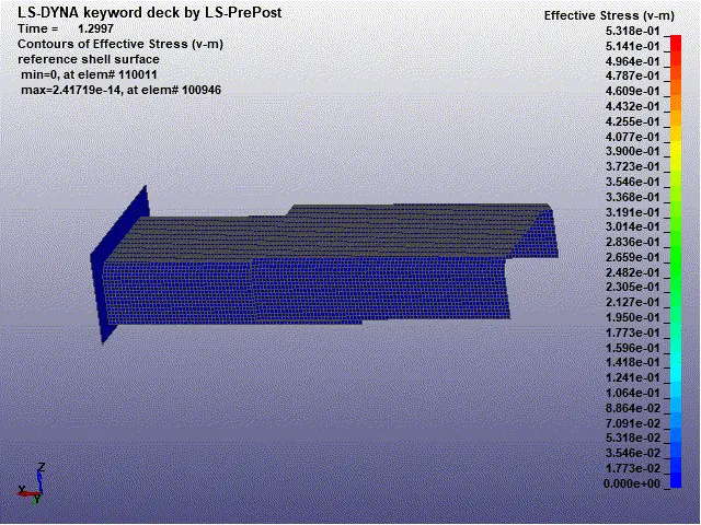
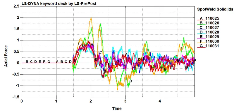
The contour plot for stress show the region where the plates are connected experience stresses. Following plot shows the axial force and later the shear forces in the spot weld solid elements are shown.
Shear Force Plot is given below,
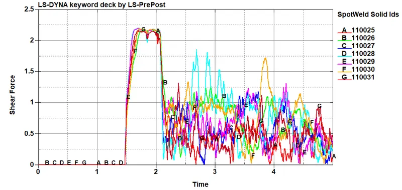
The axial force and the shear forces are pretty high in magnitude, if the stresses on the solid element are ploted this would give the idea whether the welds will fail or not. Following is the Von Misses plot for the Solid Elements of the spot welds.
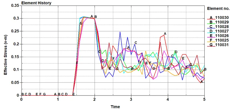
It is clear that around 1.6 ms all the spot welds pass the yield stress value (250 MPa) and hence the welds fail for this boundary condition. So the MAT SPOT weld material card can be modified such that the failure occurs at 1.6ms.
Conclusion:
In this simulation two different methods were used to model the spot welds and the results were compared. This gave understanding of the failure of the spot weld and how to benchmark the spot weld material card based on the application of the spot weld in various industry. The post processing of the spot weld i.e Axial and shear force with stresses were one of the major learning and defining the simulation in LS Dyna