Assignment 5
Title: Study of Crash Tube Analysis with different types of contact interfaces and the effect of a notch on the structure using Hypercrash and Hypermesh RADIOSS
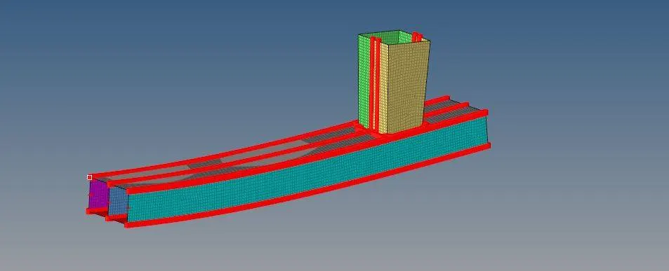
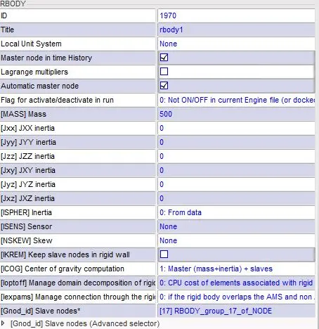
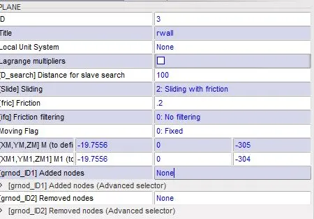
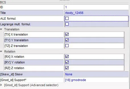
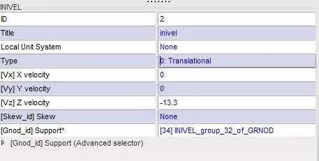
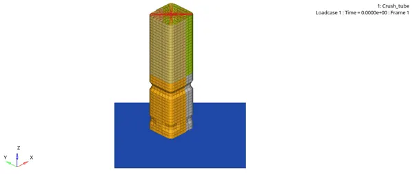
The model is a simple Crash Tube at one end of which a rigid body is considered with the circumferential nodes to be considered as slave nodes. Initial Velocity of -13.3 `mm`/`ms^2`. A rigid wall is considered at the other end of the crush tube, on which the total reaction force will be observed to see the differences in the structure with different cases. The following images show the properties used for Rigid Body, Rigid Wall, and Initial Velocity.
Rigid Body
Rigid Wall
Boundary Condition for RGBody
Initial Velocity
CASE 1: Model without any change
In this case, the given model is simulated without any changes.
The following are the results that are observed.
Animation:
Hypergraph Results:
Energy Curves:
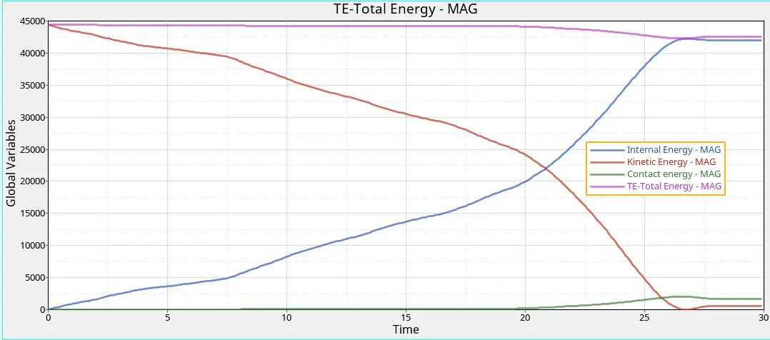
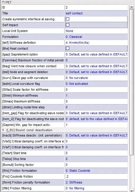
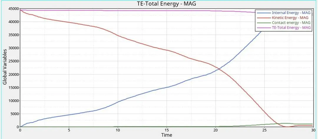
It can be observed that there is an exponential rise in internal energy up to 28ms and after that, it stays constant. This is due to, the transfer of energy after 25ms to the rigid wall, as the tube completely fails, there is no more possible for the absorption of the energy and hence the energy is transmitted. There is a consistent decrease of KE as per the conservation of energy, but a sudden rise is seen at around 28th ms and this is due to the reaction forces provided by the rigid wall. Total energy gives the sum of KE and IE with also some losses. Contact energy increases after 20ms as the elements buckle and due to the penetration of the elements the Type 7 defined contact activates, which tries to push the elements back with the creation of the springs with nonlinear stiffness. Hence the following graph depicts that there is a rise in the reaction forces at the rigid wall, After 20ms most of the force is transmitted to the wall.
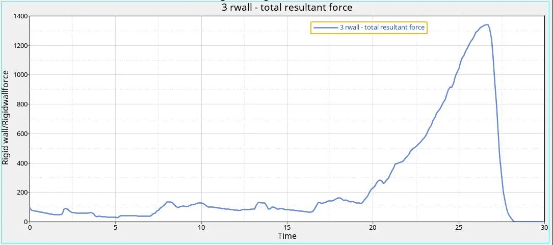
CASE 2: Inacti=6 (Variable gap with respect to time and initial penetration is considered)
Inacti=6 is the condition, in which the gap is calculated with respect to time, i.e the gap is variable with respect to time and the initial penetration is taken into consideration. Consider the example shown below,
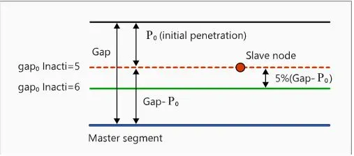
The slave node is penetrated the master segment (Gap) at Po penetration. If Inacti 6 is used the gap is reduced to accommodate initial vibration. Hence 5% of (Gap-Po) is reduced from the Gap-Po to accommodate the initial vibration of the slave nodes, So the following equation gives the gap0
`Gap0 = (Gap-P0)-5%(Gap-Po)`
Inacti 6 is activated in the Contact Interfaces window of Type7 contact.
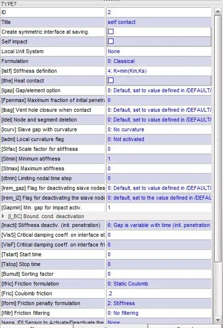
After exporting this file as a RADIOSS file, it is run and the following results are obtained.
Animation:
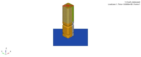
The following graph shows the energy curves for this case,
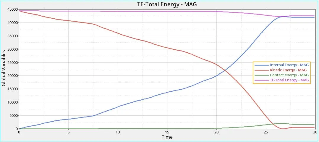
It can be clearly seen that the energy curves are similar to the Case1, this indicates that there is no initial penetration. If there were any initial penetrations the Internal Energy curve could have beginning from a non zero value. As energy is required to push the slave node(s) to put it out of the gap and hence a non zero value is seen.
CASE 3:Implementing Type 11 Contact to the Model.
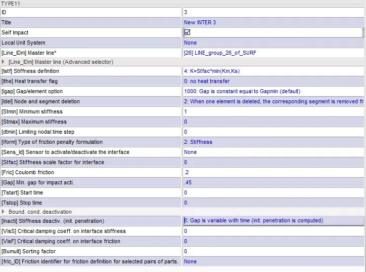
Type 11 contact is basically used to define the edge to edge contact interface between the slave and master node and vice versa. This also considers the self impacts, It is used in addition to the Type 7 contact interface.
The following table gives the parameter for the Type 11 contact interface.
Following are the results obtained from Hypergraph:
Force Curves:
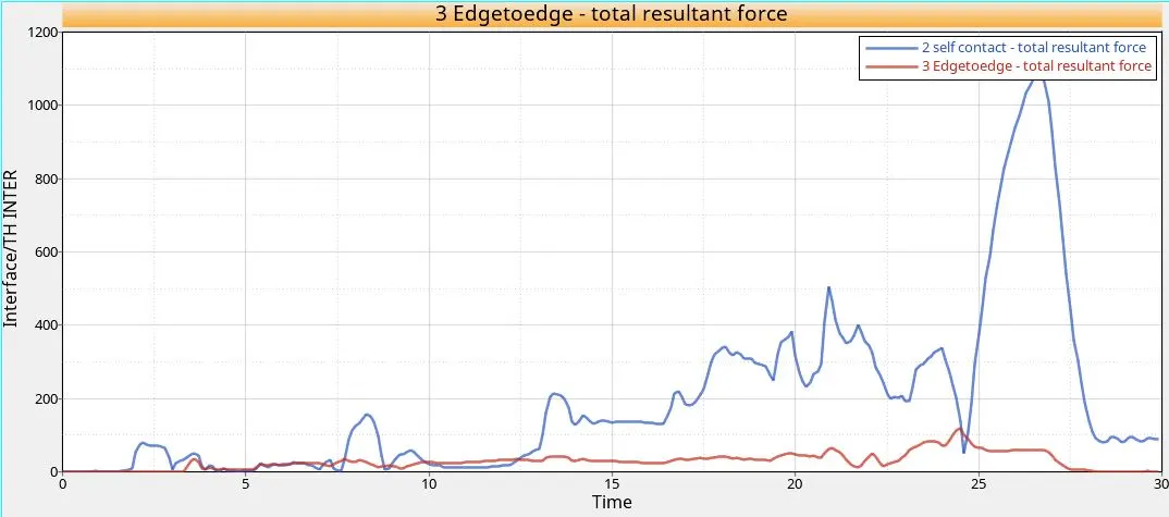
It can be seen that there is a rise in total resultant force up to 28ms as the forces are transmitted to the rigid wall, after 28ms the rebound occurs and hence the force is transmitted back to the elements and hence there is a decrease in the resultant force of the wall. The type 11 contact energy is very small in value when compared to the type 7 energy, it can be said that very less energy is involved and it doesn't affect the total resultant energy widely.
Energy Curve:
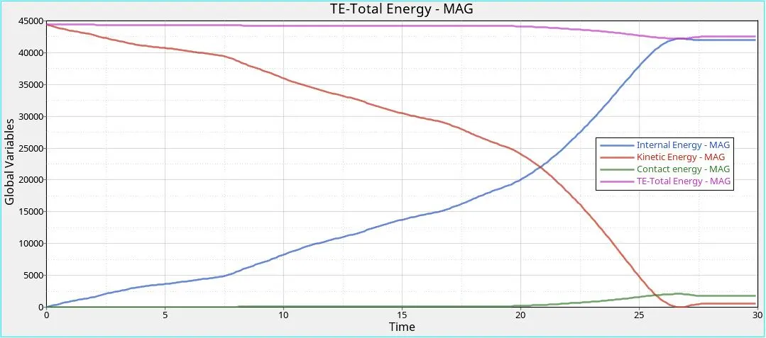
The energy curves are similar to Case 1 and Case 2. Only the Total Energy is a bit lower than previous cases, this is because of the energy lost in the edge to edge contact.
Case 4: Removal of Notches and the Boundary Condition on the Rigid Body
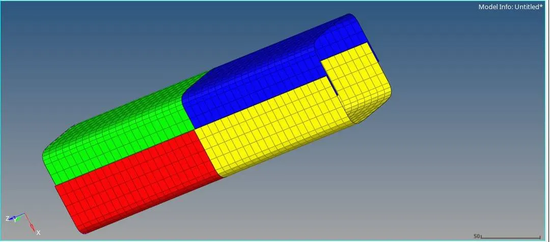
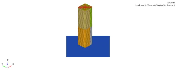
In this case, the notches are removed using Hypermesh. After removing the notches using the node align command. The Boundary Condition is removed in the Hypercrash. The CARD Boundary Condition is deleted. And this file is run on RADIOSS. Due to the removal of the BC the rigid body (node) will be free i.e, it will have DOF=6.
Following is the Animation that shows the deformation behavior of the can. The removal of the notch results in deformation from the bottom as in previous cases the deformation use to start from the notch area due to higher stress concentration factor.
Hyperview Results
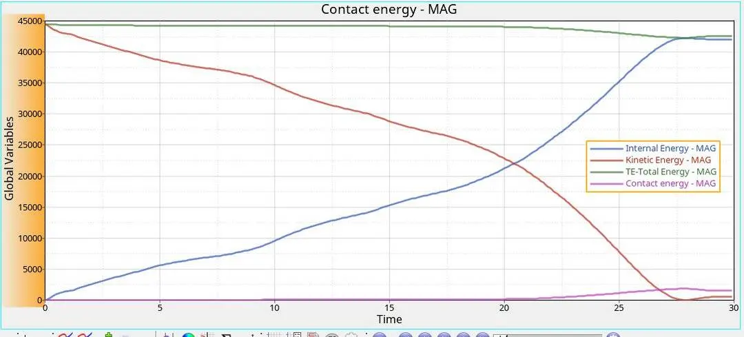
Energy Curves
As there is a decrease in the Kinetic Energy, the Internal Energy increases. The total Energy decreases in the end as some amount of energy is lost as contact energy. Contact occurs at the end part of the simulation because the solver acts against the penetration. So it tries to remove this penetration. Hence as the part of the can gets pressed against another part of the can which results in higher contact forces and we see a rise in the contact energy at the end.
Rigid Wall forces:
The rigid wall forces, in this case, are less when compared to previous cases, this is due to the removal of the BC, due to which low forces are transmitted as the can deviate when force is applied.
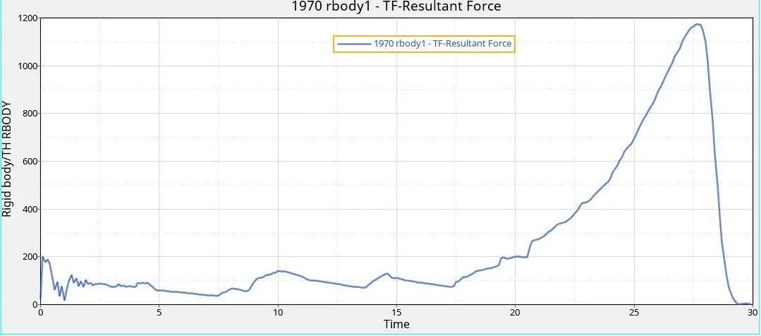
Case 5: Notch in the Middle
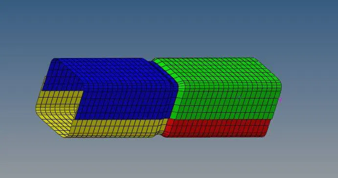
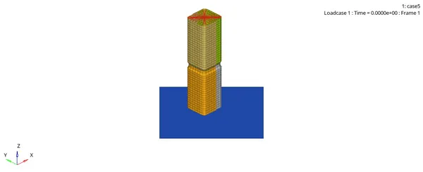
In this case, a notch is created in the middle along the circumference of the can, the behavior is observed. The geometry cleanup operation is performed on the Can using Hypermesh. And the file is run in the RADIOSS. Following are the results, As the animation file shows the failure, the bottom part gets deformed first because of high-stress concentration at the notch, so it fails there, and later the upper part fails.
Energy Curves
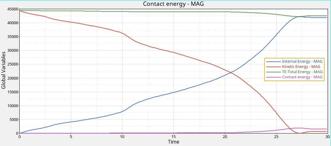
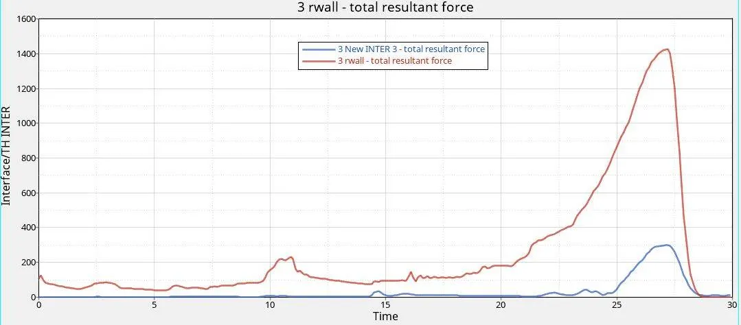
The total energy is consereved, the energy curves are almost similar to case 3,
The following are the resultant reaction forces on the rigid wall.
Case 6: Notch only on the opposite face
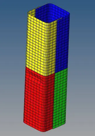
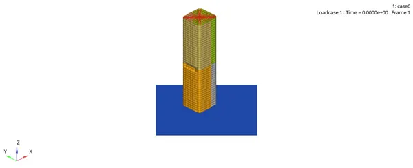
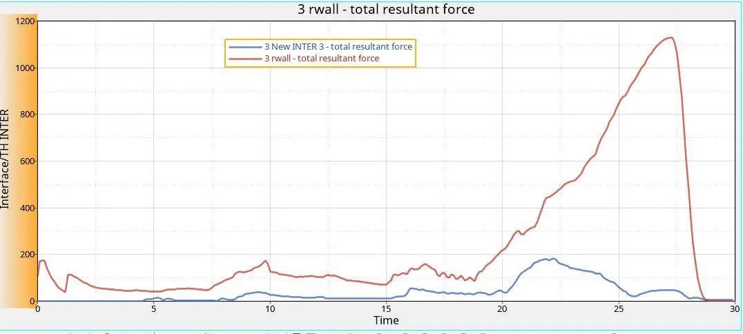
In this case, a notch is created on the opposite faces of the can in the middle portion of the can. As the area of the notch is decreased the buckling effect is reduced in this case, and compared to case 5, it is observed that resultant reaction forces are reduced on the rigid wall. The following graph shows the resultant forces on the rigid body. Also, only the sides with notch buckle and bulge, while in case 5 all the sides have outward behavior.
Energy Curves
Energy curves are quite similar to case 5, but the rate of change of Kinetic energy is less due to the presence of the notches only on two sides.
CONCLUSION:
In cases where the TYPE 7 and 11 contacts are used, higher contact energy is recorded whereas compared to only TYPE 7 is used.
Advantages of Notches:
The presence of notches helps in determining the behavior of the failure.
Disadvantages of Notches:
The structure fails at low forces when compared to the cases where no notch was present.
So in the crash application, it is really important to know the nature of the deformation as the failure nature helps in determining the safety of the component.
BUMPER MESH FILE:
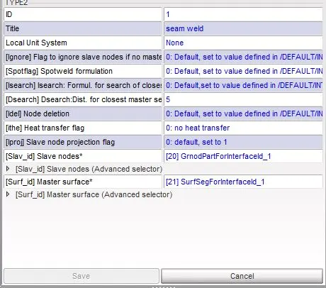
Using Hypermesh the Geometry is cleaned and the mesh operation is performed, after which weld elements are created.