Assignment 7
Fast Running Model(FRM)
FRMs execute much more rapidly than the typical detailed GT-POWER engine model, and are ideal for integrating with other vehicle systems where an accurate and predictive engine plant model is desired and where computational speed is critical. FRMs adapt to changing conditions (e.g. valve timing, spark/injection timing, turbo lag, external temperature, altitude, cooling system conditions, etc.) without the need to apply non-physical correction factors. Whether studying changes to ambient conditions, or simulating events that are heavily transient in nature, FRMs will maintain the predictive capabilities of a detailed engine model while allowing for the fast computational speeds that are expected when performing drive cycle analysis and other transient-focused simulations.
Some examples of applications that are ideal for FRMs are:
- ECU Modeling (including HiL) – where a fast-running and transient-capable engine model is essential for optimizing ECU strategy
- Engine + Drivetrain/Vehicle – where accurate torque pulsations are key for optimizing drivetrain design and strategy
- Vehicle Thermal Management modeling, where the engine provides the heat to the cooling system, and the cooling system behavior feeds back into the engine performance predictions (great for simulating off-ambient conditions)
FRMs are able to achieve such fast run times by two means: (1) increasing the simulation time step size, and (2) decreasing the number of calculations per time step. These two means are often accomplished at the same time by lumping various flow volumes together which will reduce the total number of subvolumes and also allow for a larger time step size by increasing the effective subvolume length (which is responsible for the time step size). In addition to simplifying and combining flow volumes, there are additional solver options that can reduce the number of calculations per time step and, thus, further decrease the run time without changing the time step size.
Tutorial 9 - Fast Running Model
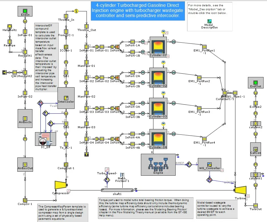
Initial FRM
Final FRM
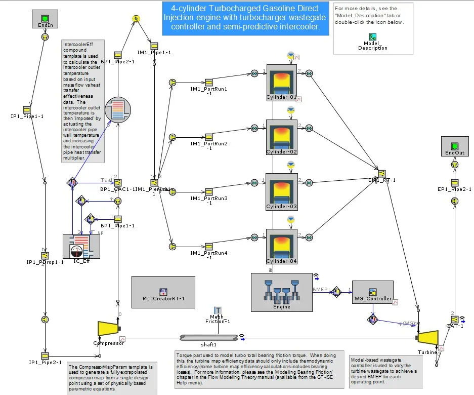
The Exhaust Manifold of the system has to modified because it is most efficient to start by simplifying the subsystem that is currently restricting the time step. For high-fidelity models, this is almost always the exhaust manifold where the highest gas velocities occur, which in turn restricts the time step. Before we apply simplifications to the exhaust manifold, the Maximum Time Step limit of 1 crank angle degree will be removed. This is a default limit that is imposed when an EngCylinder component is in the model. If the Courant Condition allows for a larger time step (by monitoring gas velocity and subvolume length in all flow components), removing this limit will allow the time step to increase in size.The Discretization Length in the pipe parts will be overwritten with an automatically created parameter called [dxe_FRM]. Its value will be set to 300mm. Port Heat Transfer dominates vs. Runner Heat Transfer, therefore a parameter for the heat transfer multiplier called [HTM_Exhaust_Manifold_1_Step_1] will be automatically created in all port/runner pipes Thermal tab. This parameter will be used to calibrate heat transfer in the combined volume to assure the Turbine Inlet Temperature is maintained.
For the second step of model simplification, the exhaust pipes downstream of the turbine will be simplified.Since the pipe at the outlet of the Turbine is rather short, this pipe will be combined with the Catalyst volumes into a single FlowSplit part.
Similiar to Exhaust Manifold,the Intake Manifold of the sytem has to be modified.Minor modifications need to be made to the Characteristic Length and Expansion Diameter attribute values for the combined volume.
The Fourth Step is the Compressor outlet pipes,since the intercooler core (previously a bundle of pipes) has been replaced with a FlowSplit and "HeatExchangerConn" part. The "HeatExchangerConn" part will be used to assure the intercooler outlet temperature is maintained.
Step 5 is the Intake Pipes.Since all the sub systems has been modified the intake pipes are simplied by giving some initial values to pipe diameters. Every subsystem has now been simplified, we will assure that there are no remaining pipes with short discretization lengths.
Step 6 is for Additional Changes done to the system. Here it is done for the exhaust manifold on "Similify for Speed" for the Mass flow rate to the Turbine and it's temperature.
The final simplification to the model will utilize the Cylinder Slaving capability of the EngCylinder component. For the full cylinder slaving to function, each Valve must be specified as either an Intake or Exhaust valve.
FRM Model Using FRM Builder Approach
Specification
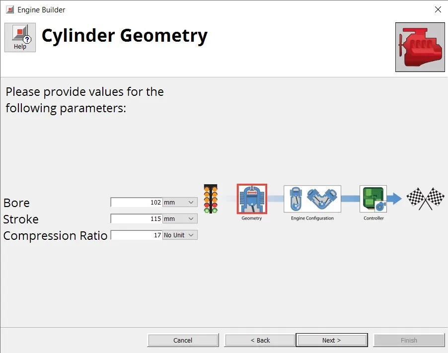
- Bore = 102 mm
- Stroke = 115 mm
- CR = 17
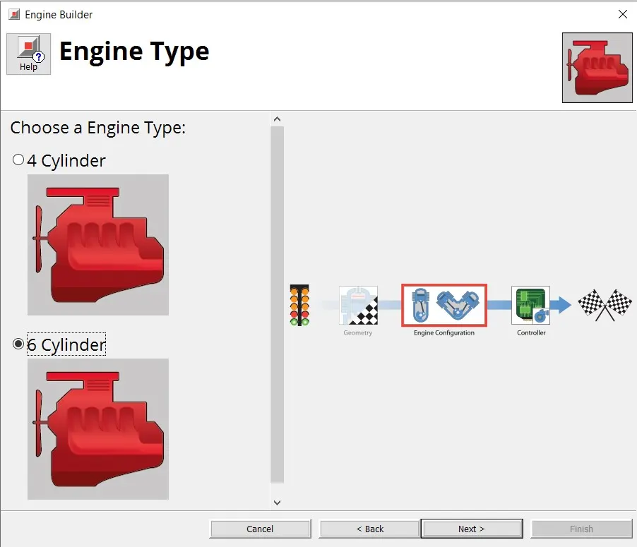
- No of cylinder = 6
- CI engine
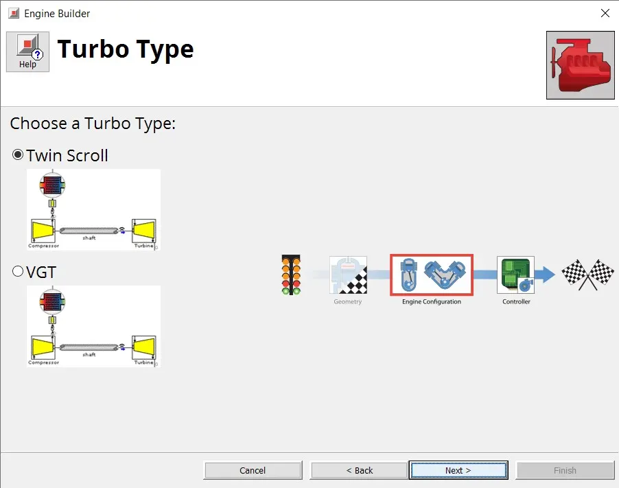
- Twin Scroll Turbine
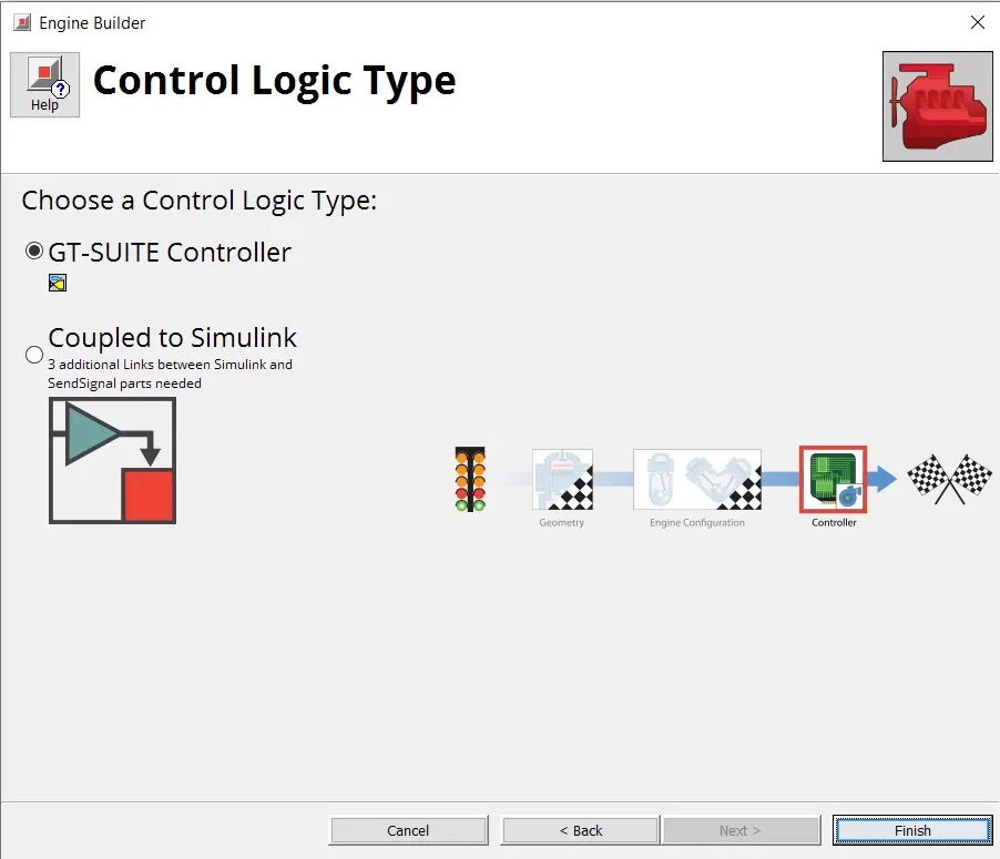
- GT Controller
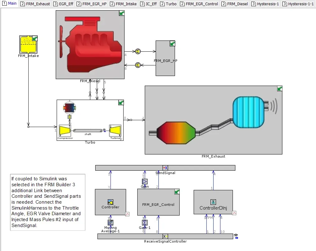
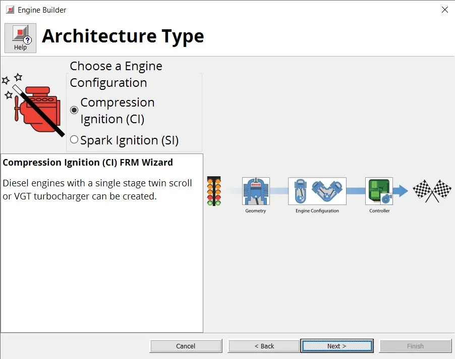
The FRM bulider has template which is used to model an engine either 4 cylinder or an 6 cylinder engine with a turbocharger type either Twin Scroll or Variable Geometry Turbocharger.With control logic type of GT-Suite Controller or Coupled to Simulink.
Architecture Type
Cylinder Geometry
Turbocharger Type
Engine Type
- Control Logic Type
In running all the case, we have achieved the requried BMEP of the specific cases.
Engine Performance for this model can viewed below:
https://drive.google.com/file/d/1au-OjVrMJwdy4zylGINNA-XJexXMVU2H/view?usp=sharing
Result
- Thus FRM performs the simulation rapidly when compared to the detailed model of same specification.
- Also we studied the FRM model and how it is been structured.