What Is Combinational logic circuits?
Logic gates are the simplest combinational circuits. A combinational logic circuit is a circuit whose outputs only depend on the current state of its inputs. These circuits realize Boolean functions and deal with digitized signals, usually denoted by 0s and 1s.
 Skill-Lync·12 Jun 2023·2 min read

Combinational logic circuits
Logic gates are the simplest combinational circuits. A combinational logic circuit is a circuit whose outputs only depend on the current state of its inputs. These circuits realize Boolean functions and deal with digitized signals, usually denoted by 0s and 1s.
The behavior of a combinational circuit is memoryless; given a stimulus to the input of a combinational circuit, a response appears at the output after some propagation delay, but the response is not stored or fed back. The output depends solely on its most recent input and is independent of the circuit’s past history.
There are three basic logic gates-
- AND
- OR
- NOT
The universal logic gates are-
- NAND
- NOR
Let us try implementing combinational circuits in Simulink.
Example:1
For the expression -
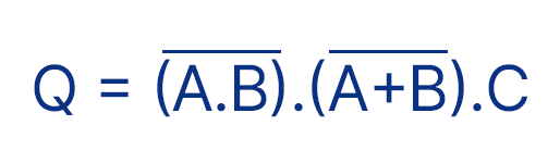
Here,
- Q is the output.
- A, B, and C are the inputs that take the binary values of 0 and 1.
- The bar represents the complement of itself. The complement of 0 is 1, and vice versa.
- The product represents the AND operation; the addition represents the OR operation.
Steps of solving:
- Write the truth table. If the number of states is n, then the output calculated is 2^n. Here there are three states, A, B, and C the total output that can be realized is 2^3=8.
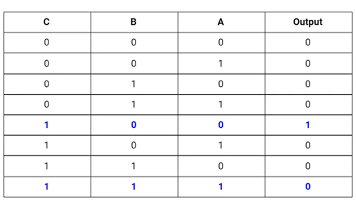
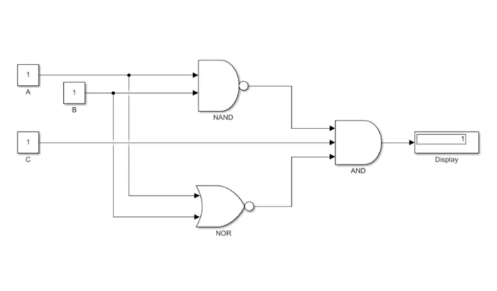
- Realize the number of gates required. This particular example can be solved in different ways. To make it simpler, we will use NAND, XOR, and AND gates.
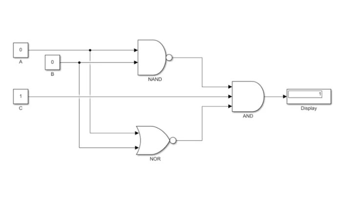
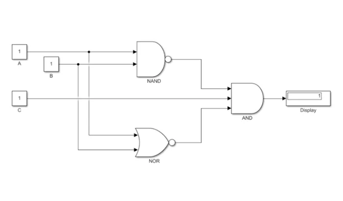
- The complement of (A.B) can be realized using the NAND gate directly. (A+B) complement can be performed using the XOR gate.
- The Simulink model for the logic gate implementation is given below.
When, A=0, B=0, C=1
When A=1, B=1, C=1
Example:2
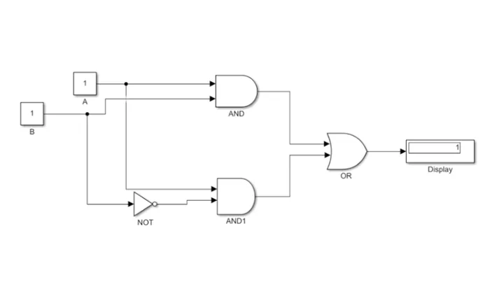
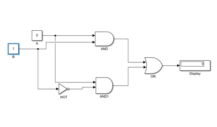
For the expression- F=(A.B)+(A.B’)
1) Truth table
2. For this equation, we have chosen two AND gates, one Not gate to represent B complement, and an OR gate.
3. Simulink model for the logic gate implementation is given below
For A=1, B=1
For, A=0, B=1
Thus the logic gates for the combinational circuits have been computed.