Modeling a Li-ion Battery Equivalent Circuit
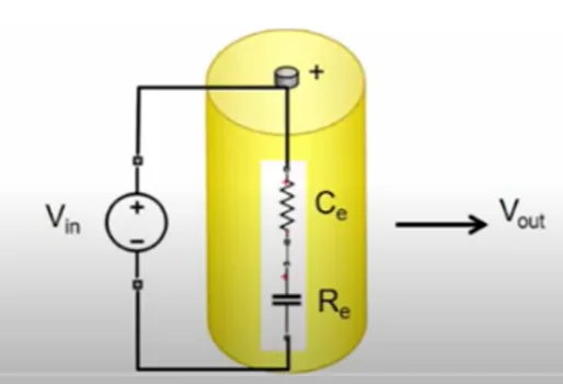
An equivalent circuit refers to a circuit component to form a specific circuit network to characterize the circuit's operational characteristics. It is important for the analysis of its performance and to discover any scope of further modification of modeling.
 Navin Baskar·28 May 2023·2 min read
Modeling a Li-ion Battery Equivalent Circuit
The objective of the article is to model the Li-ion battery equivalent circuit in Simulink. This model represents the battery characteristics of its voltage and current.
An equivalent circuit refers to a circuit component to form a specific circuit network to characterize the circuit's operational characteristics. It is important for the analysis of its performance and to discover any scope of further modification of modeling. It is a very useful way of understanding or predicting the operation and behavior of an electrical circuit.
How to get the block from simulink is explained below.
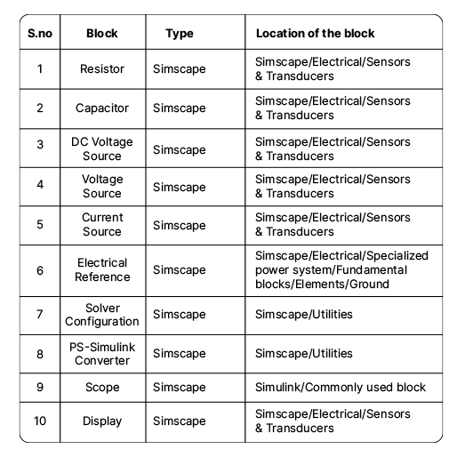
First, open the simulink blank model. The shortcut to get the blocks is to double-click on the blank space of the model window and type the name of the block in the search tab. Also you need to check the path of each block you are choosing.
The blocks and their location in the library browser is given below in the table.
The PS-simulink converter blocks help to connect the simscape block and simulink block.
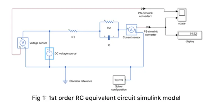
The 1st order RC equivalent circuit simulink model is shown in fig 1. The controllable voltage (DC voltage source) denotes the open circuit voltage of the lithium-ion battery which usually varies nonlinearly with SOC, R1 denotes the ohmic resistance of the lithium-ion battery which describes the electrolyte resistance and connection resistance of the battery, R2 denotes the polarization resistance (Polarization resistance is the transition resistance between the electrodes and the electrolyte), C denotes polarization capacitance (Polarization capacitors are the ones that have specific positive and negative polarities). The parallel RC network describes the nonlinear polarization response of the lithium-ion battery, and I is positive for discharging and negative for charging.
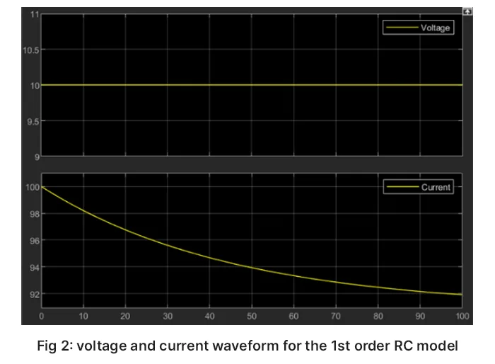
The voltage and current waveform for the 1st order RC model is shown in fig 2. The voltage is shown as 10V in the graph, because DC voltage is taken as 10V. The current is calculated and displayed as 91.92A.
The 2nd-order RC equivalent circuit Simulink model is shown in Fig 3. Where Vdc, R1, R2, R3, C, and C1 have the same meanings as in the first-order RC model, except that there are two parallel RC networks to describe the nonlinear polarization response of the lithium-ion battery.
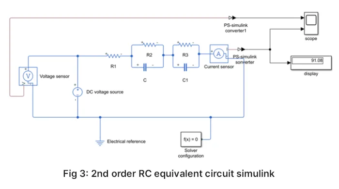
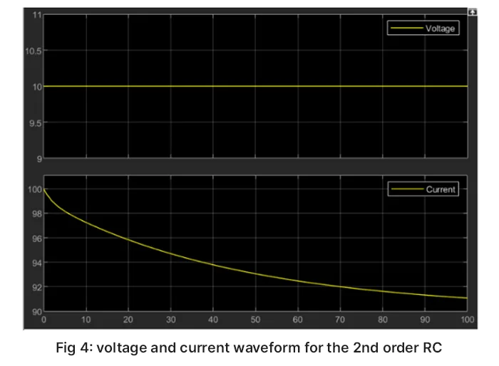
The voltage and current waveform for the 2nd order RC model are shown in Fig 4. The voltage is 10V, as the DC voltage source is given as 10V. The current is calculated and displayed as 91.08A
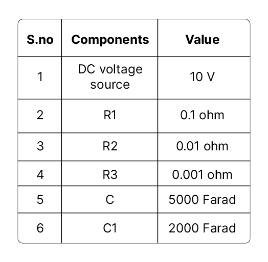
The value taken in the Simulink model is given below.
- In the first-order RC model, there is no resonance, and there is only a time constant for charging /discharging.
- In the second-order RC model, there is resonance, and the system can oscillate according to the damping of the circuit.
Application:
- Automotive
- Aerospace
- Consumer electronics
- Renewable energy
- Electricity grid