Modified on
Why Do Intersections Errors Happen While Defining a Volume For A 3D Mesh ?

Skill-Lync
Meshes are primarily composed of two distinct entities: the geometry (the position x, y, and z of the nodes) and also the topology (how the nodes are connected).
What is a Mesh?
A mesh may be a network that's formed of cells and points. It can have almost any shape in any size and is employed to unravel Partial Differential Equations. Each cell of the mesh represents a personal solution of the equation (all unknowns of equations) which, when combined for the entire network, ends up in an answer for the whole mesh.
Solving the complete region without dividing it into smaller pieces is impossible due to the complexity involved within the domain. Holes, corners and angles can make it extremely difficult for solvers to get an answer. Small cells, on the opposite hand, are comparably easy to unravel and so is the popular strategy.
How Do Intersection Errors Show Up in a 3D Mesh?
- Below mentioned image shows the error pop-up:
_1667401824.png)
Let’s understand it with the help of an example.
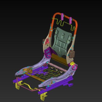
The component shown below has two parts included in it.
_1667401850.png)
Penetration: Intersections error occurs during a volume mesh when you have defined volumes (Volume deck > Volumes > Define) of two parts together as a single Volume list.
Note: You can see a list of volumes defined by doing V.Mesh > Volume > List. (Refer to Figure 3).
This error may also come when there is a common surface for two different parts (i.e Triple CONS in the model) or if the surfaces of two components are very close together.
_1667401885.png)
Now Right click on the selected ID 1 and select “Remesh”. (Refer Fig.4)
_1667401913.png)
You will be able to see the error pop-up which shows the Penetration: Intersections error as Shown in Fig 1.
__________________________________________________________________________________________________________________________________________
Now let's solve the above issue by defining the volume for both part volumes separately.
Step 1:
- Define the volume for the inner separated part volumes as shown in Fig 5.
- Isolate one part alone in GUI
- Goto Volume deck > Volumes > Define > Manual
- Select the whole part
_1667401959.png)
- On a middle click confirmation you will see a Property help window popping up.
- Then follow these steps to create a new PID for Volume: Right click > New > PSOLID
- You can see a window popping up which asks to enter the details of the PSOLID.
_1667401985.png)
- Rename it and click Ok.
- Now you can see that a PSOLID Id is created on the Property help window.
_1667402019.png)
- Double-click on the Id and the property will be assigned to that newly created PID.
- Now open the Volumes > List tab from the volume deck, you can see the following pop-up window.
_1667402047.png)
- Right-click on the Id and select Remesh.
_1667402076.png)
- You can see another window popping up where you can select the type of mesh generation algorithm.
_1667402125.png)
- Select Tetra FEM and select Ok.
- Now if we check the Volumes > List, it shows the status as Meshed.
_1667402147.png)
- Follow the same steps to mesh the other outer part.
Author

Navin Baskar
Author
Skill-Lync
Subscribe to Our Free Newsletter

Continue Reading
Related Blogs
Learn how to render a shock-tube-simulation and how to work on similar projects after enrolling into anyone of Skill-Lync's CAE courses.
09 May 2020
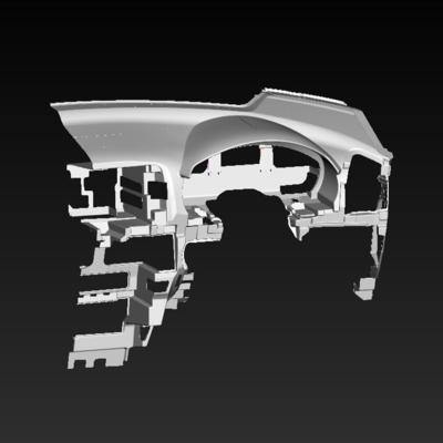
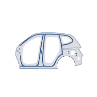
In this blog, read how to design the frontal BIW enclosure of a car (Bonnet) and learn how Skill-Lync Master's Program in Automotive Design using CATIA V5 will help you get employed as a design engineer.
09 May 2020
Tetrahedral is a four- nodded solid element that can be generated through the tria element by creating a volume and also through the existing volume of the geometry. These elements are used where the geometry has high thickness and complexity. The image attached below is a representation of a Tetra element. The Tetra element will have 4 triangular faces with four nodes joining them together
01 Aug 2022
A connector is a mechanism that specifies how an object (vertex, edge, or face) is connected to another object or the ground. By often simulating the desired behaviour without having to build the precise shape or specify contact circumstances, connectors make modeling simpler.
02 Aug 2022
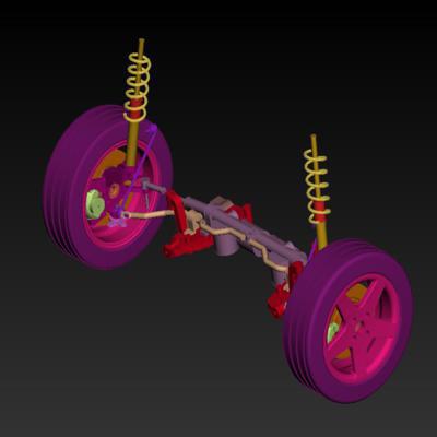
One of the most crucial processes in carrying out an accurate simulation using FEA is meshing. A mesh is composed of elements that have nodes—coordinate positions in space that might change depending on the element type—that symbolise the geometry's shape.
03 Aug 2022
Author
Skill-Lync
Subscribe to Our Free Newsletter
Continue Reading
Related Blogs
Learn how to render a shock-tube-simulation and how to work on similar projects after enrolling into anyone of Skill-Lync's CAE courses.
09 May 2020
In this blog, read how to design the frontal BIW enclosure of a car (Bonnet) and learn how Skill-Lync Master's Program in Automotive Design using CATIA V5 will help you get employed as a design engineer.
09 May 2020
Tetrahedral is a four- nodded solid element that can be generated through the tria element by creating a volume and also through the existing volume of the geometry. These elements are used where the geometry has high thickness and complexity. The image attached below is a representation of a Tetra element. The Tetra element will have 4 triangular faces with four nodes joining them together
01 Aug 2022
A connector is a mechanism that specifies how an object (vertex, edge, or face) is connected to another object or the ground. By often simulating the desired behaviour without having to build the precise shape or specify contact circumstances, connectors make modeling simpler.
02 Aug 2022
One of the most crucial processes in carrying out an accurate simulation using FEA is meshing. A mesh is composed of elements that have nodes—coordinate positions in space that might change depending on the element type—that symbolise the geometry's shape.
03 Aug 2022
Related Courses