Modified on
All about Draft Analysis using Catia

Skill-Lync
The draft analysis technique is used to analyze whether our part model created in CAD is manufacturable based on the draft condition applied. Here the part should get easily removed from the panel dies (in case of Sheet metal part) or Mold (in case of plastic).
No parts can be ejected from the tool if it is having a straight 90-degree profile from its base surface. A small draft angle is provided to each and every area of the component in order to get easy removal of the component from the tool.
Here we are providing a direction in which components should eject in order to get easy removal of components from the tool. In other words, it also lets us know whether the model is having a draft angle and how much is the draft angle from the tool direction.
The Types of Components for Draft Analysis
Draft analysis is performed on the components where the ejection of materials happens after the material is made inside the tools. In the case of Automotive Sheet Metal manufacturing, the blank sheet after turning into automotive panels like Hood, Fender, Roof, Side Doors, Back Doors etc. need to be removed from Panel Dies. If a considerable amount of draft angle is not provided, the removal of components from the tool will be difficult. It’s the same in the case of mold(plastic component) after getting filled inside the core and cavity, it needs to get ejected easily with the help of ejectors.
_1658241584.png)
Procedure To Perform A Draft Analysis in Catia
_1658241631.png)
Step 1
Change the view mode to Customize View Parameters and select the Material option from the Mesh.
_1658241696.png)
_1658241720.png)
Step 2
Next, you need to create a rough line, without considering a particular direction or parameters. The direction of the line may vary from component to component. To make the Draft Analysis easier, it will be better if the line is created from the CG point.
For that, we need to select the measure inertia option from the measuring toolbar.
_1658241792.png)
After that select the body from the tree for the Measure Inertia dialogue box.
_1658241877.png)
The CG point is represented inside a box on the intersection point of red, blue, and green. If we want to get to that point permanently, we need to select the created geometry and select both the center of gravity and the Axis system.
Step 3
Create a random line from the CG point using the point and direction option from the line command.
_1658241940.png)
Step 4
Draft Analysis options are available inside the following workbenches:
- Part Design
- Generative Shape Design
- Wireframe and Surface for Building
- FreeStyle Shaper
Insert > Analysis > Draft Analysis
The draft Analysis dialog box with colour scale (with quick analysis mode) appears on the screen. So the first mode option is the quick analysis mode and the second is the full analysis mode. Here the quick analysis mode is used.
_1658242033.png)
Change the value of green according to the draft angle provided to the part. Here for automotive sheet metal components, the ideal draft angle is 7 degrees.
Step 5
Drag the compass and place it over to the line.
_1658242135.png)
_1658242173.png)
Select the compass icon from the direction of the Draft Analysis dialog box. The compass may get misplaced from its original position after clicking on the compass icon.
_1658242216.png)
Select the compass again and place it over to the line properly one more time.
_1658242259.png)
Step 6
After placing it, click anywhere on the part.
_1658242322.png)
The appearance of the component will change afterwards.
_1658242361.png)
To get a clear picture, either we need to adjust the compass by holding the marked region of the compass and dragging it towards the opposite direction or by selecting the inverses draft direction option inside the direction of Draft Analysis
_1658242405.png)
_1658242437.png)
_1658242476.png)
_1658242512.png)
Step 7
After getting the green colour on the component, try to adjust the compass using the knob, and adjust the direction of the compass to get green on the entire top panel region.
_1658242581.png)
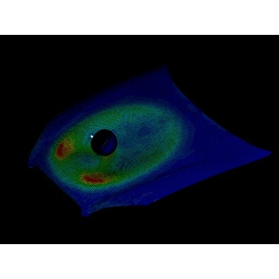
Try zooming in and checking if each and every region of the panel is showing green, if in some regions, red or blue is showing instead of green, those negative regions are below 7 degrees and have no draft applied on those regions.
_1658242635.png)
Those blue and red negative regions need to be changed.
Step 8
If we are ok with the result, right-click on the compass and lock its current position using lock current orientation.
_1658242719.png)
Step 9
Click ok to the draft analysis dialog box to close it. Double click on the line and right click on the direction option and change the line direction to compass direction. The line will get oriented along with the previously locked compass draft direction.
_1658242798.png)
After the use, right-click again on the compass and unlock it. Also, reset the compass using the shortcut Alt + v + r. The compass will get reset to its original position. Later we can provide thickness to the line and change the appearance colour to green by right-clicking and selecting properties (which is an ideal colour used to represent draft direction).
_1658242849.png)
Exploring More Display Options
Show or Hide the Colour Scale
The first option inside the display is to show or hide the colour scale. This option is used to change the draft angle value according to the type of component used.
_1658242894.png)
Analysis under the Running Point
This option is used to highlight the exact draft angle of that face. For that, we need to move the point along the faces.
_1658242948.png)
No Highlight Representation / Light Effect
No Highlight Representation and Light Effect options are used to change the view type to get a clear highlight of the Draft Analysis result.
Draft Analysis of Plastic Components
The ideal draft angle for the plastic components is 3 degrees. This may vary according to the functional requirement. Apart from the draft angle consideration, the remaining procedures for the draft analysis are similar to the above-mentioned steps. The draft angle provided for the plastic features is 0.5 degrees. This may also get varied accordingly.
_1658243024.png)
The above figure shows the tooling direction, slider direction, dog house slider direction, and snap slider direction of the plastic component. This is determined with the help of draft analysis with a draft angle of 0.5 degrees.
_1658243071.png)

Author

Navin Baskar
Author
Skill-Lync
Subscribe to Our Free Newsletter

Continue Reading
Related Blogs
Explore the fundamentals of vehicle dynamics and ultimate trends in the field from design and modeling to control with Skill Lync's exclusive course on the subject. Read about how Skill-Lync's CAE courses can help you get employed.
28 Jul 2020
In this article, we will briefly discuss the working, applications, and features of the one-dimensional systematic simulation tool, GT-Power, in Emission Control Strategy, engine calibration, hybrid vehicle modeling. Read about how Skill-Lync's CAE courses can help you get employed.
28 Jul 2020
This article offers a brief introduction to the globally accepted standard of Geometric Dimensioning and Tolerancing, and its importance for the entire manufacturing process. Read about how Skill-Lync's CAE courses can help you get employed.
28 Jul 2020
In this blog we will read about Going a step into Biomechanics and how Skill-Lync's CAE course will help you get employed.
09 May 2020
The powertrain is the most prominent source of vibrations that affects the driving experience for the people on board. This blog from Skill-Lync examines these vibrations to help enhance that experience.
21 Aug 2020
Author
Skill-Lync
Subscribe to Our Free Newsletter
Continue Reading
Related Blogs
Explore the fundamentals of vehicle dynamics and ultimate trends in the field from design and modeling to control with Skill Lync's exclusive course on the subject. Read about how Skill-Lync's CAE courses can help you get employed.
28 Jul 2020
In this article, we will briefly discuss the working, applications, and features of the one-dimensional systematic simulation tool, GT-Power, in Emission Control Strategy, engine calibration, hybrid vehicle modeling. Read about how Skill-Lync's CAE courses can help you get employed.
28 Jul 2020
This article offers a brief introduction to the globally accepted standard of Geometric Dimensioning and Tolerancing, and its importance for the entire manufacturing process. Read about how Skill-Lync's CAE courses can help you get employed.
28 Jul 2020
In this blog we will read about Going a step into Biomechanics and how Skill-Lync's CAE course will help you get employed.
09 May 2020
The powertrain is the most prominent source of vibrations that affects the driving experience for the people on board. This blog from Skill-Lync examines these vibrations to help enhance that experience.
21 Aug 2020
Related Courses