Wiring harness routing & packaging Rules Week 3 Challenge
Objective:
- To download the P-Clamp CAD data and define it as Electrical Support in the Electrical Part design workbench and define the necessary electrical properties.
- To download the Back-shell CAD data and define it as Electrical Back shell in the Electrical Part design workbench and define the necessary electrical properties.
- To create Following Corrugated tubes and add them in Catalogue under “Slit COT” family.
Name ID (mm) OD (mm) Thickness (mm)
15mm COT 12 15 1.5
20mm COT 17 20 1.5
35mm COT 32 35 1.5
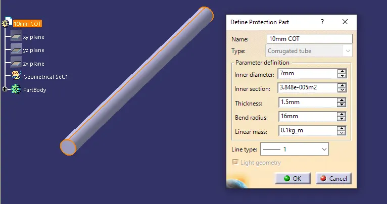
10mm COT 7 10 1.5
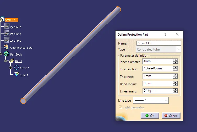
5mm COT 3 5 1
- P - Clamp:
P-Clamp is an Electrical Support equipment which provides support to the wire bundle to remain fixed to any component or part.
- The wire bundle can enter and exit from any side as it is a bi-directional equipment.
Therefore, it is necessary to define Entry and Exit planes from both the sides along with a base plane as reference.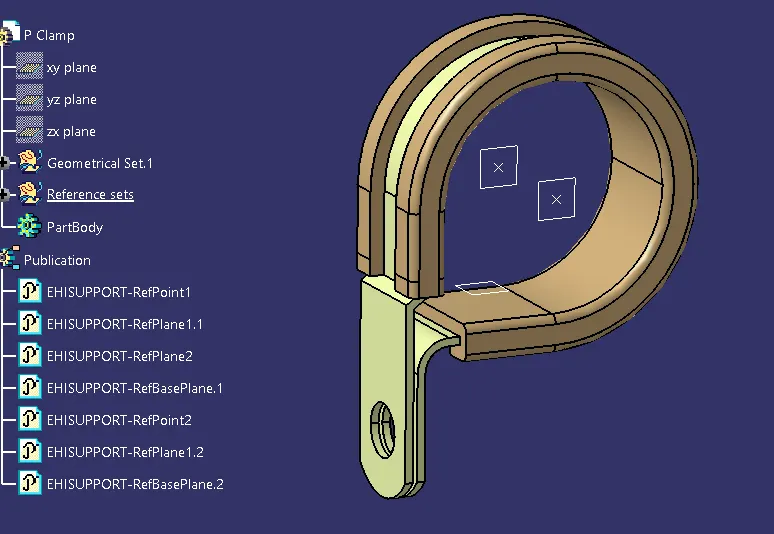
To define the P-Clamp as Electrical Support equipment
- Download the CAD part and open it using the CATIA V5 software.
- Then we need to create points and planes at the entry and exit points, along with base plane as reference.
- In the electrical part workbench, using the 'Define support part' option we can define the P-Clamp Entry and Exit planes.
As the P-Clamp is Bi-directional so we need to define the support two times.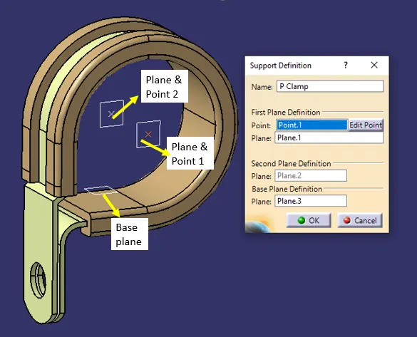
- Back-Shell:
A Back-shell is an additional equipment that mounts to the rear threads of a connector to enhance its operational characteristics. Primarily, Back-shell provides strain relief, which minimizes stress from the cable, on the junction where the wires terminate to the contacts.
For material compatibility and aesthetics, Back-shells and connectors should have a matching material and finish.
To define the Electrical properties of the Back-shell
- First download the 3-D CAD part of the Back-shell and open it using the CATIA V5 software.
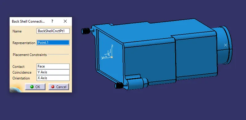
- Place necessary points to define the bundle connection point and back-shell connection point. And provide an axis system on the Back-shell connection side.
- Define the component as Back-shell in the electrical part design workbench.
Bundle connection point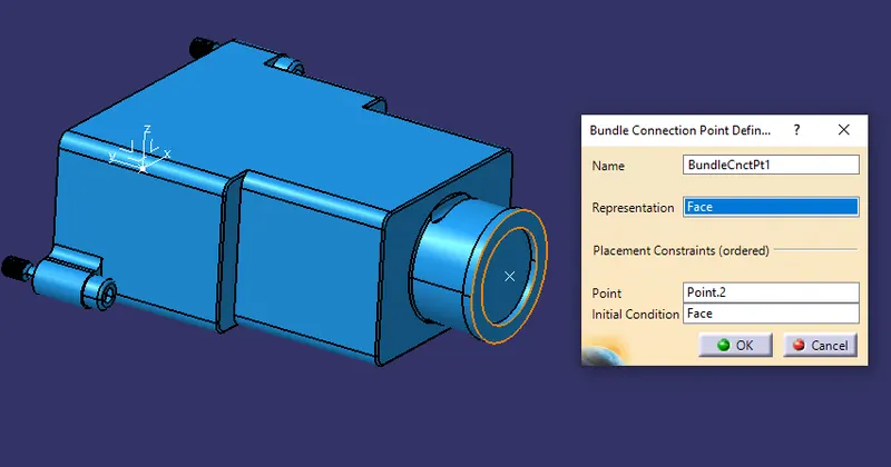
Back-shell Connection Point:
Defining Bach-shell connection Axis
- X-axis: Towards the locking mechanism of connector.
- Y-axis: Towards the front face of connector.
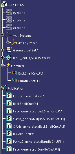
Tree Structure:
- Corrugated Tubes:Corrugated Tubes are used as protective covering for the wire bundle from any type of damages and heat resistance.
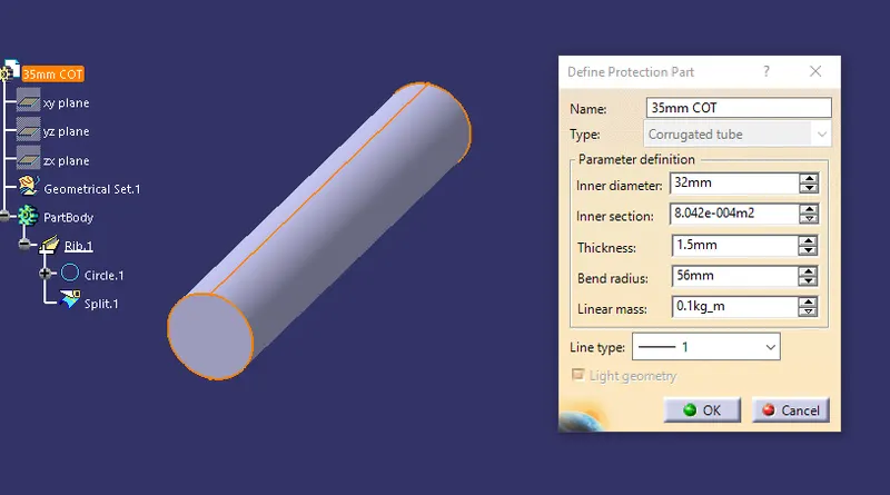
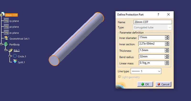
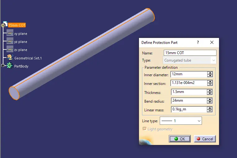
To define Corrugated tube, in the electrical part design workbench, choose define Protection part command.
Give the inner diameter, thickness and Bend radius - 35 mm Cot Tube:
- 20 mm Cot Tube:
- 15 mm Cot Tube:
- 10 mm Cot Tube:
- 5 mm Cot Tube:
Creating Corrugated Tube Catalogue:
- Just like Assembly file (Product file) and Part file there is a separate file available for Catalogue called CatalogDocument. Create a new CatalogDocument.
- Inside that, Use the add Family command.
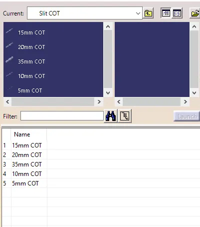
- The type of the family should be taken as Conduit. And name should be given as Slit COT. Save and exit the file.
- After creation of each corrugated tube as a separate part file, they should be added to the catalogue.
- In the electrical part design workbench, Choose Store Device option, navigate the file location in Catalog definition and choose the family Slit COT and press OK. The part will be added to the Catalogue.
Conclusion:
This project is aimed at understanding and defining support equipment like P-Clamp as an electrical equipment, Defining Back-shell as an electrical equipment and creating Corrugated tubes of various sizes and defining them in a catalogue for ease of access.