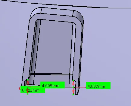
Week 10 - Challenge 2- Attachment Feature Creation (Dog House)
Tooling Axis Creation
1. Extract a flat surface from the Door Trim. Create a point on the center of the extracted surface. Draw a normal line to the surface. This line is taken as the tooling axis for the Door Trim.
Here it is convinient for us to create a tooling axis directly rather than following the bisecting method.
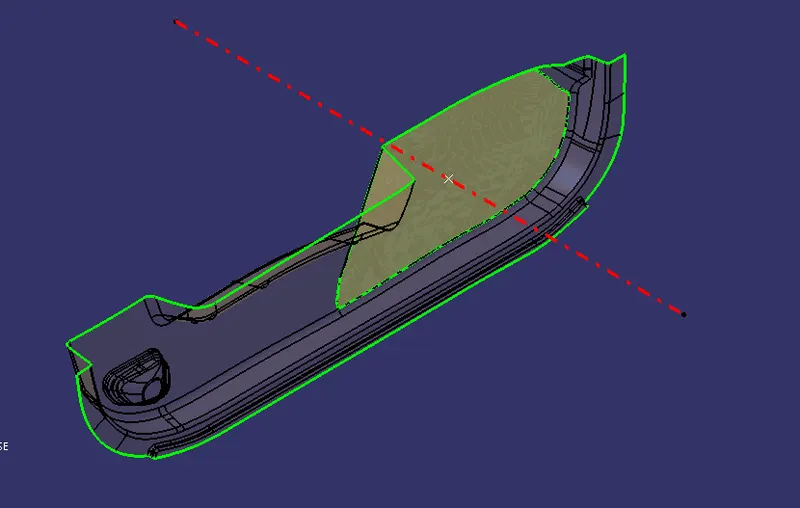
Draft Analysis
1. Change meshing mode to "material" in the view mode dialog box.
2. Click on draft analysis option.
3. Zoom out and locate the compass, drag and drop the compass to coincide the tool axis to define the new current draft direction.
4. Choose the class A surface/ Solid part to perform draft analysis.
5. Under display option, use the colour scale to analyze the dynamic draft of the component.
CLASS A Draft Analysis
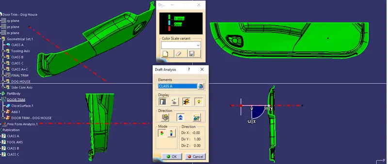
Draft Analysis Solid Part with Dog House Feature
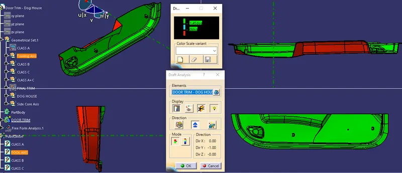
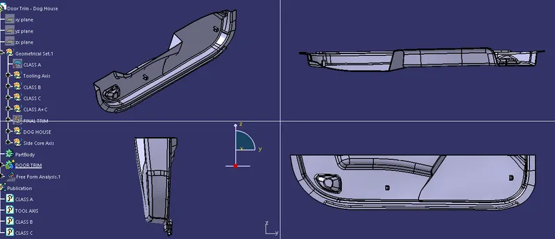
Door Trim in different views
Dog House parameters
1.
B= 0.724 (< 40% of 2.5mm)
C1 = 4.64mm
C2 = 4.5mm
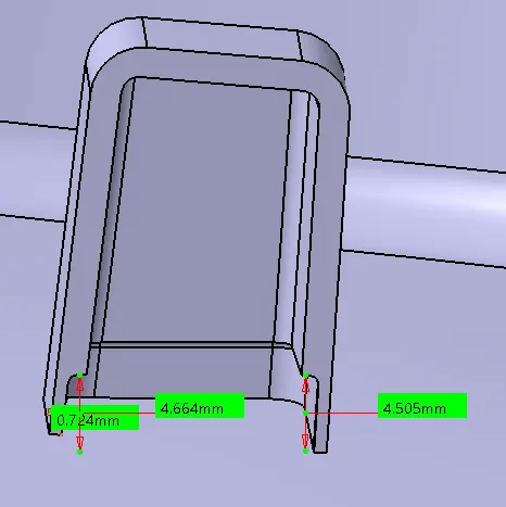
2.
B= 0.724 (< 40% of 2.5mm)
C1 = 4.0mm
C2 = 4.0mm