Week 10 - Challenge 1- Attachment Feature Creation (Ribs & Screw Boss)
Tool axis Creation
1. Extract a surface as reference and create a point on the center of the extracted surface.
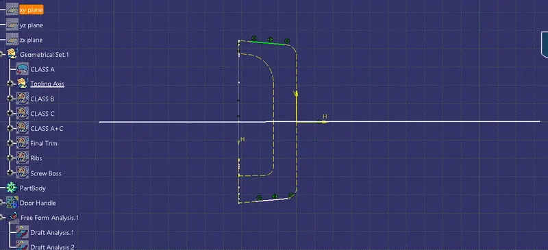
2. Inorder to clear tooling path along Y direction, Use Project 3D elements command on XY plane with the Class A surface. Consider the outer walls and extend the lines.
3. Create a bisecting line by choosing the two extended lines on the outer walls. The bisecting line formed is the tooling axis.
Draft Analysis
1. Change meshing mode to "material" in the view mode dialog box.
2. Click on draft analysis option.
3. Locate the compass, drag and drop the compass to coincide the tool axis to define the new current draft direction.
4. Choose the class A surface/ Solid part to perform draft analysis.
5. Under display option, use the colour scale to analyze the dynamic draft of the component.
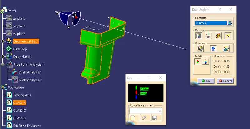
- Given some faces has very less draft angle, the draft angle is considerd to be 0.5 degrees to pass the draft analysis
Draft Analysis Class A
Draft Analysis Solid Part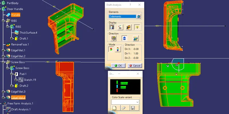
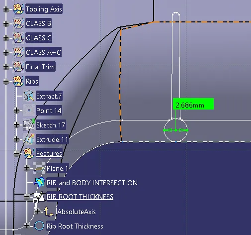
Rib Root analsyis
Create a tri-tangent circle considering the filleted edges and base edge of the part.
A deviation of +/- 30% of the thickness of the component is acceptable