Wiring harness routing & packaging Rules Week 3 Challenge
AIM:
To solve the above assignment questions and define the necessary electrical properties in the respective workbench.
OBJECTIVE:
- To download the P-Clamp CAD data and define it as Electrical Support in the Electrical Part design workbench and also define the necessary electrical properties.
- To download the Backshell CAD data and define it as Electrical Back shell in the Electrical Part design workbench and also define the necessary electrical properties.
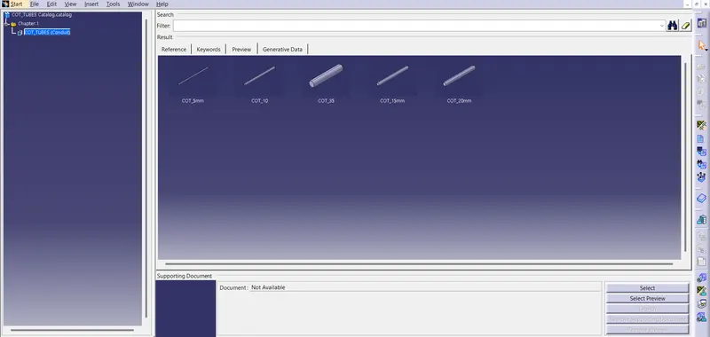
- To create Following Corrugated tubes and add them in Catalogue under “Slit COT” family.
|
Name |
ID (mm) |
OD (mm) |
Thickness (mm) |
|
15mm COT |
12 |
15 |
1.5 |
|
20mm COT |
17 |
20 |
1.5 |
|
35mm COT |
32 |
35 |
1.5 |
|
10mm COT |
7 |
10 |
1.5 |
|
5mm COT |
3 |
5 |
1 |
SOLUTION METHODOLOGY:
1.P Clamp :
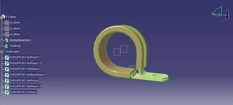
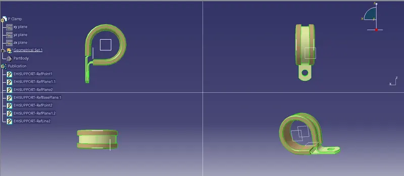
P Clamps lock Cables and Hoses in Place and help Ensure that machinery , Vehicles and equipment keep running. They Bracket wires, Cables or hoses together mechanically and are fastened securely to an anchor point - usually with a Screw or a Bolt.

PRECEDURE STEPS:
- First download the CAD part and open it using the CATIA V5 software.
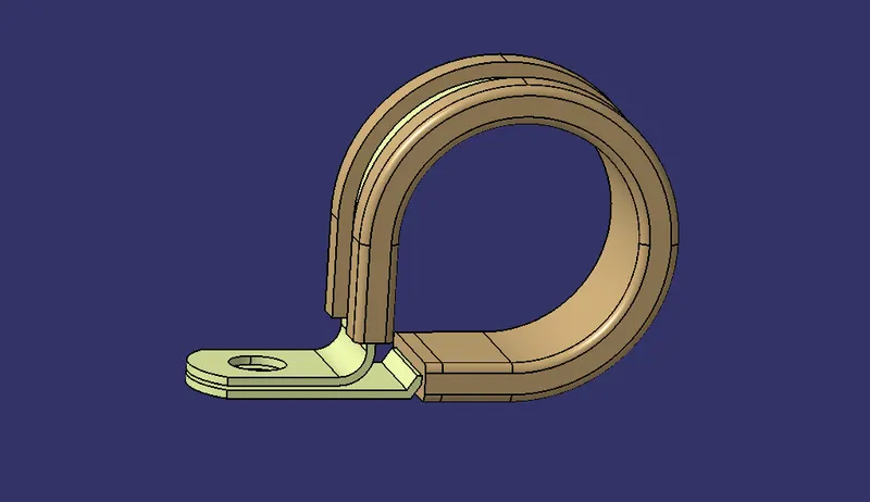
- Now we have to define the geometry parameters.
- In order to define the geometry parameters, we need to navigate to the Part Workbench.
- Then we need to create points and plains at the entry and exit points.
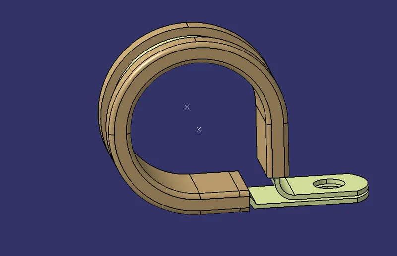
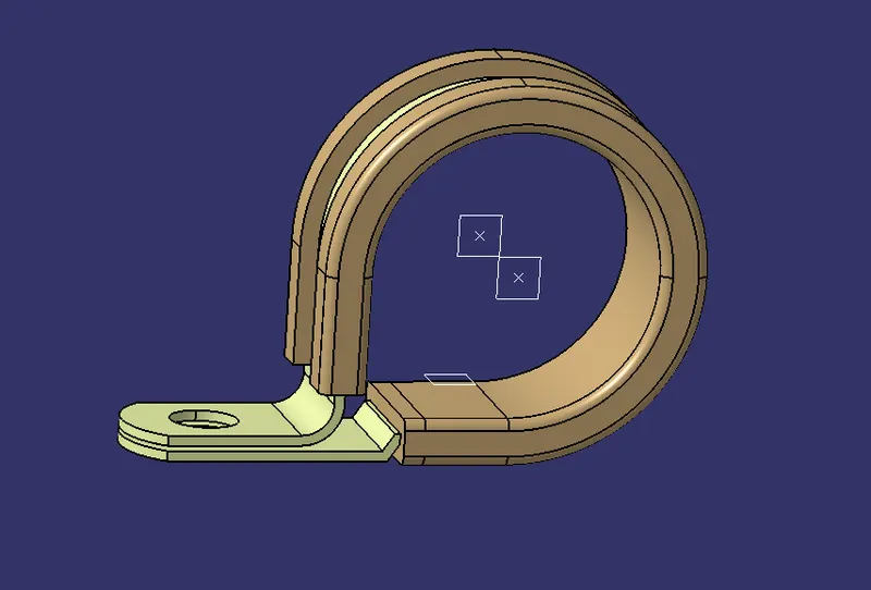
- Now in order to define the P-Clamp as a Electrical support we have to navigate to the Electrical Part design Workbench.
- Now using the 'Define support part' option we can define the P-Clamp Entry and Exit points.
- As the P-Clamp is Bi-directional so we need to define the support two times.
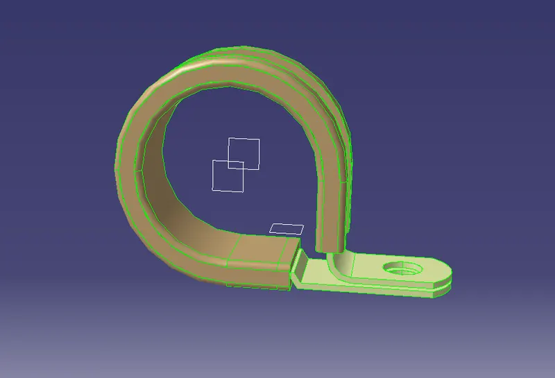
TREE STRUCTURE:
MULTIPLE VIEWS:
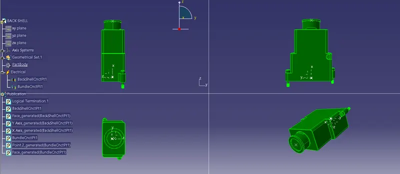
2. BACKSHELL
It is a Rear Portion Of Onnector , Usually enveloping the Connector Housing, Designed to Provide additional Support and Protection for the Connector and its cable coming out of the back of the Connector.
Procedure For Defining Backshell Electrically :-
First of all we have to download the igs or step file of Tyco 1738312-1 Backshell. After that, Extract it and Create two Points Point 1 is mating Connection Point & point 2 is Bundle Connection Point. After that Create One Axis System & go to Electrical Part Design and Define the Electrical Properties.
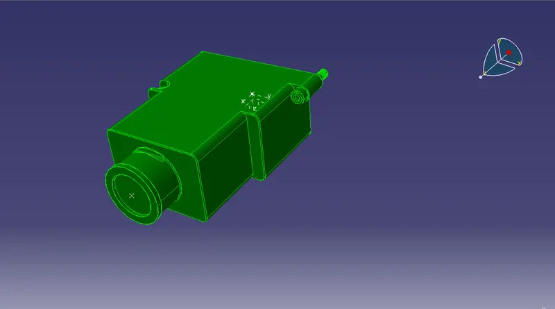
TREE STRUTURE:
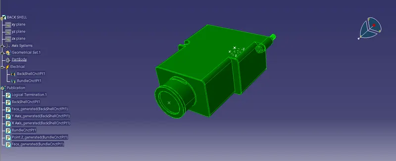
MULTIPLE VIEWS:
3.Corrugated Tubes
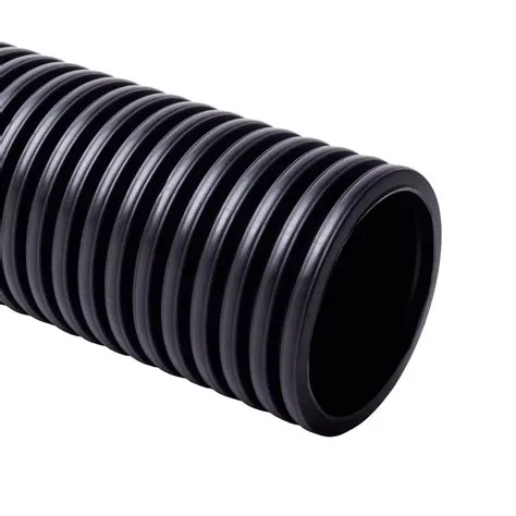
A Corrugated Tube is a Pipe with a helical groove obtained from a Plain tube by Cold forming. The number of starts of the helix can be changed as well as the angle to optimize the heat transfer and performance.
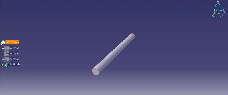
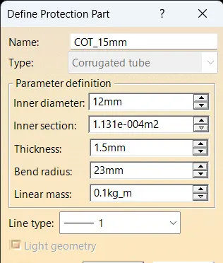
- Creating the following corrugated tubes as per the dimensions given in the table and storing in the Slit COT family catalogue document.
|
Name |
ID (mm) |
OD (mm) |
Thickness (mm) |
|
15mm COT |
12 |
15 |
1.5 |
|
20mm COT |
17 |
20 |
1.5 |
|
35mm COT |
32 |
35 |
1.5 |
|
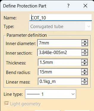
10mm COT |
7 |
10 |
1.5 |
|
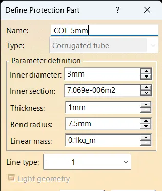
5mm COT |
3 |
5 |
1 |
1. 15 mm COT TUBE:
2. 20 mm COT TUBE:
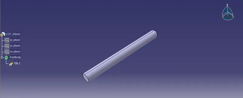
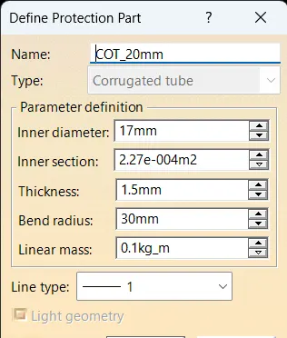
3. 35 mm COT TUBE:
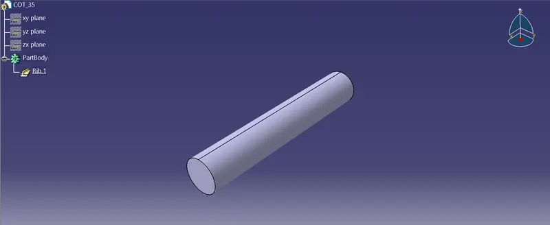
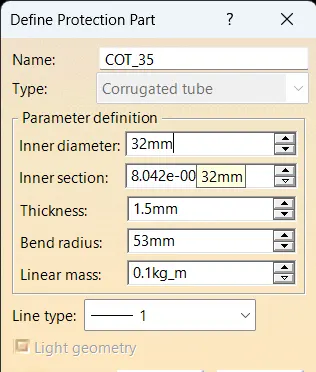
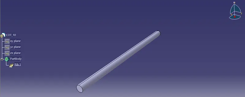
4. 10 mm COT TUBE:
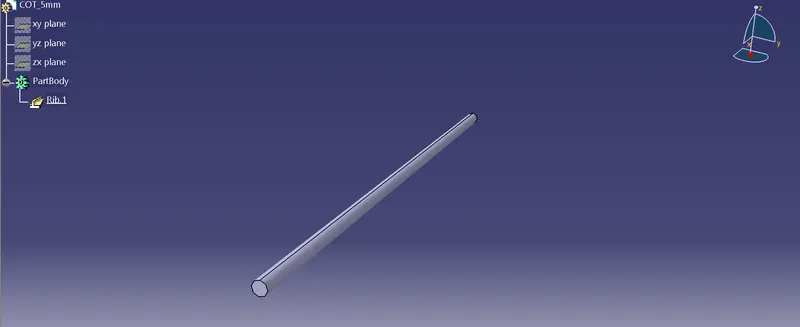
5. 5 mm COT TUBE:
CORRUGATED TUBE CATALOGUE:
CONCLUSION:
- From the above assignment we learnt how to define the Electrical support for a P-Clamp and also define its Electrical properties.
- We also learnt how to Electrical Backshell for a Backshell component and also define its Electrical properties.
- We also learnt how to make Corrugated Tubes of different diameters and also save them in the respective families in the Corrugated Tubes catalogues.