Wiring harness routing & packaging Rules Week 3 Challenge
|
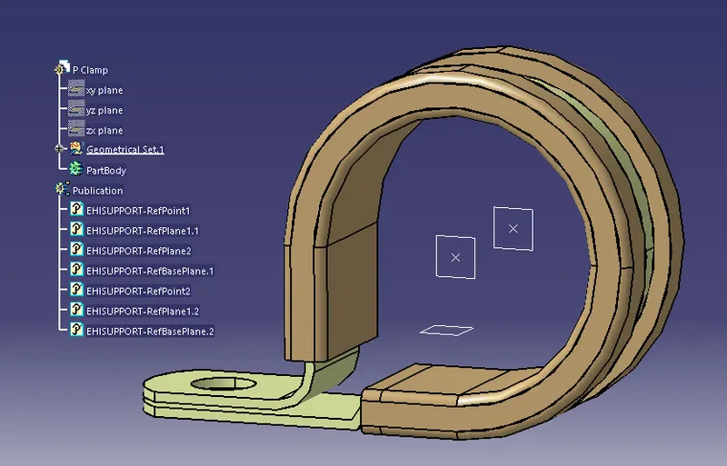
In this Slide, P Clamp is geometrically defined. 1st load cad file in CATIA V5, then open Part Design work bench, define 1st points on center of the clip from where bundle entry and exit point. After location point on bot side, locate plane on both sides with reference of earlier located points. and then locate a base plane. After all geometry is given to P Clamp, switch part design workbench to Electrical Part Design work bench. There we have to define part as as define support part. Once "Define Support part" command is selected, then select the Clip. Define properties as First Plane Defination (Point & Plane) Second Plane Defination (Select Another Side Plane) Base Plane defination (Select Base Plae) Same process to be follow from another side and define all properties. So that entry of bundle and exit of bundle can be possible from both sides of clip. |
|
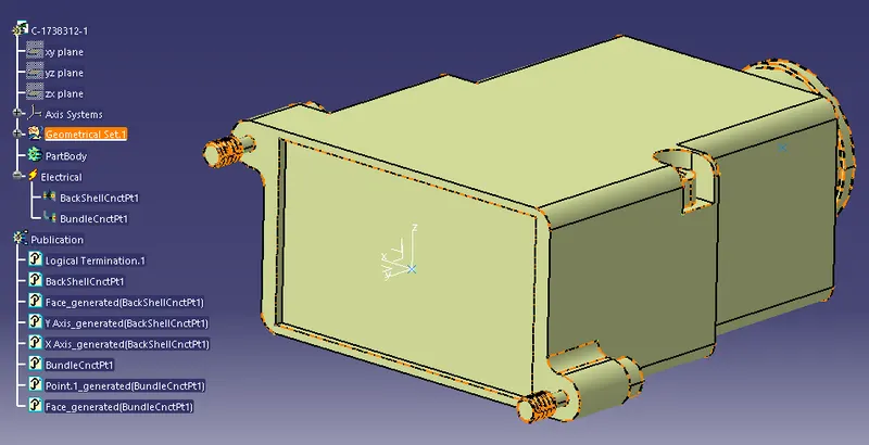
In This Slide, Backsheel 1738312-1 is geometrically and electrically defined. 1st load cad file in catia, then in part design work bench, locate point on centre of both side of backshell i.e. Budndle connection point and backshell connection point. Then define axis system on backsheel connection point for sucessfully mating of backshell with connector. where Y axis pointing towards coincidence, X axis defined as orientation and Z axis is pointing towards UP side. (In connector where this backsheel to be mate, same geometry to be difine for connector also). After define axis system, Switch workbench to electrical part design and define component as a backshell. After this, define Backshell connection point where Y axis to be kept as Coincidence axis, X axis is orientation and Z axis point on up side. After this, define bundle connection point, where representation will be face, point will be center point and initial contact will be again face. With all this properties, we can mate backshell with connector. |
|
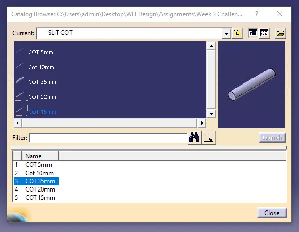
In this slide, i created catalogue for COT Tubes under SLIT COT family, for that select electrical part design workbench, create new part then select Define Protection Part command an then select part or part body, Specification window will open in which inner dia and thickness to be mention. bend radius should be 1.5 of outer dia (inner dia multiply by 2*thickness) Same process to be done for all cot which we have to create. Then a new catalog to be created and family and specify name as we want. I kept SLIT COT as mentioned in assignment. Then Select Standard as Conduit, also select conduit as standard for part family. Then Save catalog. After saving Catalog, all cot tube 1st save in system at any location, then save in catalog via Store Command. There select folder via browse and then select family and save cot tubes in catalog whihc we need for futher use. |