Wiring harness design in CATIA V5 - 3D modeling Week 5 & 6 Challenge
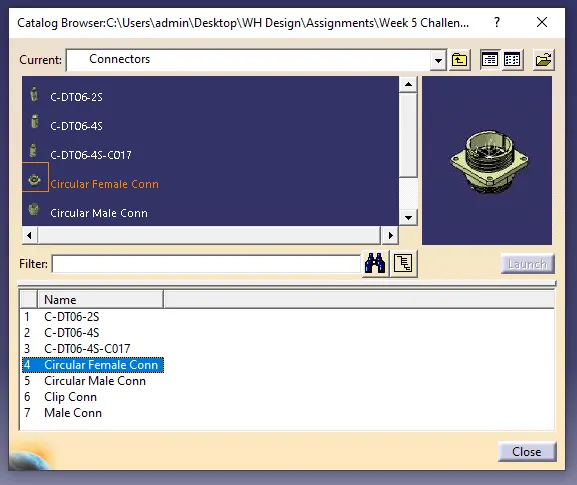
In above slide, electricaly defined connector is saved via store device command, for that from toolbar, in file, catalog document to be create and select add family then select category as electrical. then save all the electrical connectors in catalg for further easy use.
---------------------------------------------------------------------------------------------------------------------
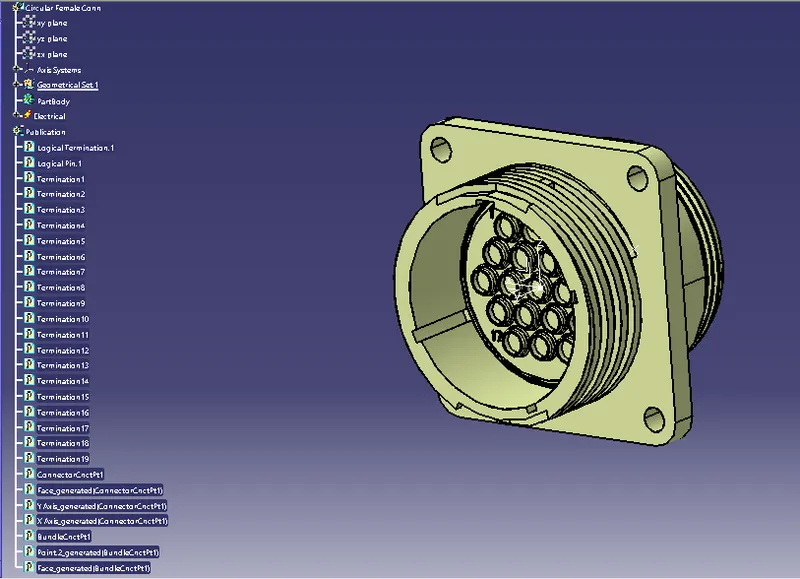
In above slide, 1st in part design workbench connector c-213870-1 is geometrically defined. 1st creatd center point on mating face of connector and bundle entry face of the connector.
Then define axis system on connector mating face wrt connector connection point. Where Y axis is on coincidence side, X axis is on left side of the connector and Z axis is on the top side of the connector.
In this slide, switched workbench from part design to electrical part design. Define component as a 19 pole connector. Then give property as a connector connector point where representation point is center point of axis system, contact is face side, coincedence is Y axis, orietation is X axis. Then give property as bundle connection point, where Contact is face, point is center point.
As shown all properties are given and connector is now deinfed as electrical.
---------------------------------------------------------------------------------------------------------------------
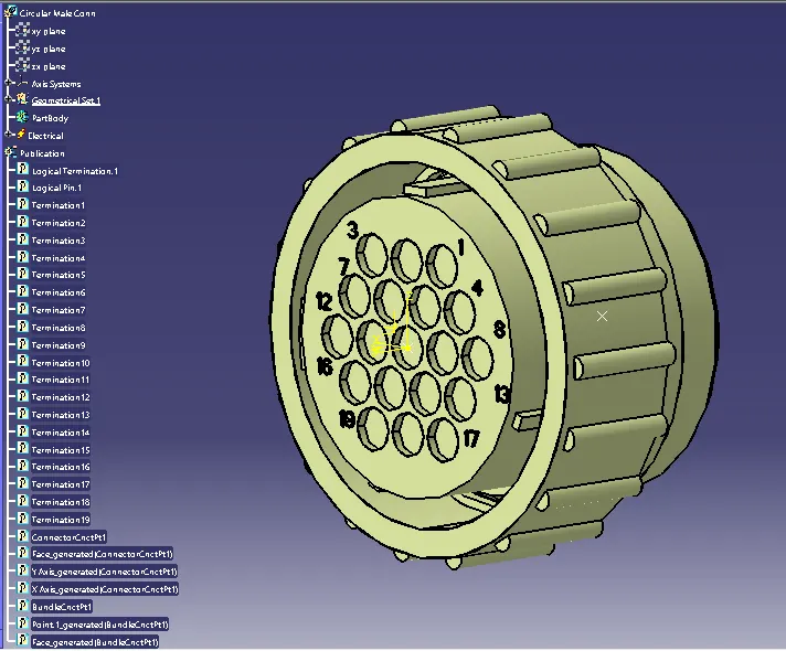
In above slide, 1st in part design workbench connector c-0213853-01 is geometrically defined. 1st creatd center point on mating face of connector and bundle entry face of the connector.
Then define axis system on connector mating face wrt connector connection point. Where Y axis is on coincidence side, X axis is on left side of the connector and Z axis is on the top side of the connector.
In this slide, switched workbench from part design to electrical part design. Define component as a 19 pole connector. Then give property as a connector connector point where representation point is center point of axis system, contact is face side, coincedence is Y axis, orietation is X axis. Then give property as bundle connection point, where Contact is face, point is center point.
As shown all properties are given and connector is now deinfed as electrical.
---------------------------------------------------------------------------------------------------------------------
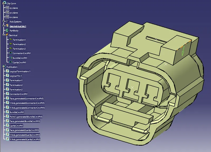
In above slide, 1st in part design workbench connector c-1-174357-2 is geometrically defined. 1st creatd center point on mating face of connector and bundle entry face of the connector.
Then define axis system on connector mating face wrt connector connection point. Where Y axis is on coincidence side, X axis is on left side of the connector and Z axis is on the top side of the connector.
In this slide, switched workbench from part design to electrical part design. Define component as a 03 pole connector. Then give property as a connector connector point where representation point is center point of axis system, contact is face side, coincedence is Y axis, orietation is X axis. Then give property as bundle connection point, where Contact is face, point is center point.
As shown all properties are given and connector is now deinfed as electrical. After that to mount clip on connector, cavity connection point defined by usig axis system, where coincidence will be Y axis, orientation is X axis and Z axis towards mating side of connector.
--------------------------------------------------------------------------------------------------------------------
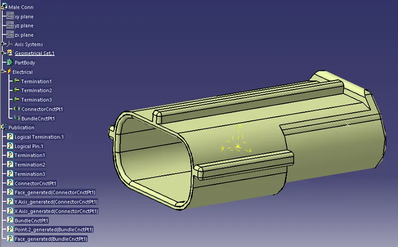
In above slide, 1st in part design workbench connector c-174359-2 is geometrically defined. 1st creatd center point on mating face of connector and bundle entry face of the connector.
Then define axis system on connector mating face wrt connector connection point. Where Y axis is on coincidence side, X axis is on left side of the connector and Z axis is on the top side of the connector.
In this slide, switched workbench from part design to electrical part design. Define component as a 03 pole connector. Then give property as a connector connector point where representation point is center point of axis system, contact is face side, coincedence is Y axis, orietation is X axis. Then give property as bundle connection point, where Contact is face, point is center point.
As shown all properties are given and connector is now deinfed as electrical.
-------------------------------------------------------------------------------------------------------------------
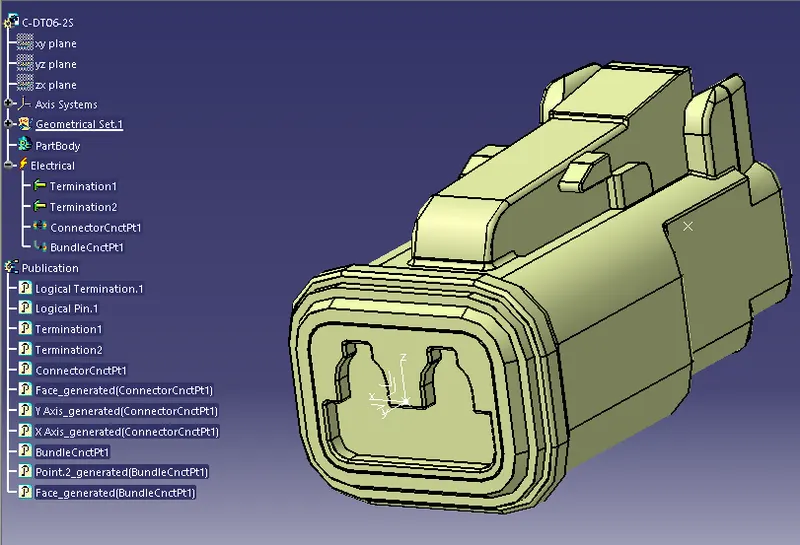
In above slide, 1st in part design workbench connector C-DT06-2S is geometrically defined. 1st creatd center point on mating face of connector and bundle entry face of the connector.
Then define axis system on connector mating face wrt connector connection point. Where Y axis is on coincidence side, X axis is on left side of the connector and Z axis is on the top side of the connector.
In this slide, switched workbench from part design to electrical part design. Define component as a 2 pole connector. Then give property as a connector connector point where representation point is center point of axis system, contact is face side, coincedence is Y axis, orietation is X axis. Then give property as bundle connection point, where Contact is face, point is center point.
As shown all properties are given and connector is now deinfed as electrical.
---------------------------------------------------------------------------------------------------------------------
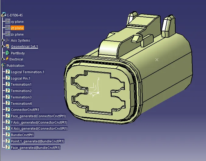
In above slide, 1st in part design workbench connector C-DT06-4S is geometrically defined. 1st creatd center point on mating face of connector and bundle entry face of the connector.
Then define axis system on connector mating face wrt connector connection point. Where Y axis is on coincidence side, X axis is on left side of the connector and Z axis is on the top side of the connector.
In this slide, switched workbench from part design to electrical part design. Define component as a 4 pole connector. Then give property as a connector connector point where representation point is center point of axis system, contact is face side, coincedence is Y axis, orietation is X axis. Then give property as bundle connection point, where Contact is face, point is center point.
As shown all properties are given and connector is now deinfed as electrical.
---------------------------------------------------------------------------------------------------------------------
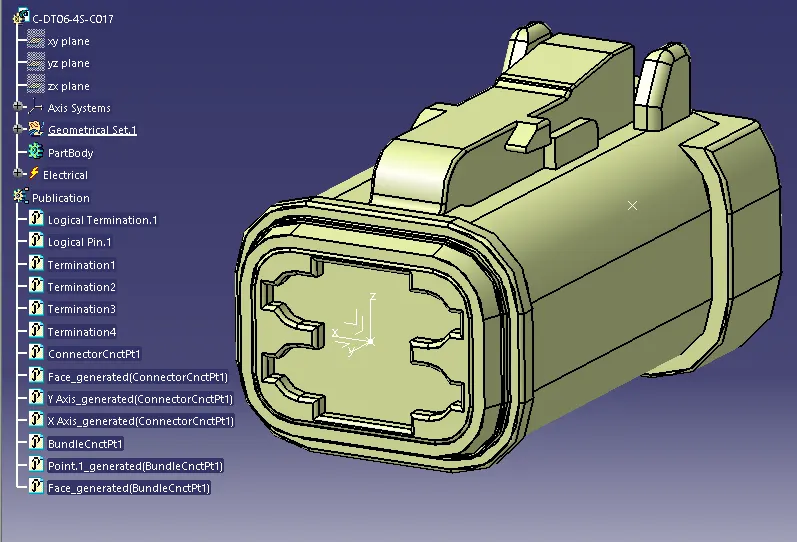
In above slide, 1st in part design workbench connector C-DT06-4S-CO17 is geometrically defined. 1st creatd center point on mating face of connector and bundle entry face of the connector.
Then define axis system on connector mating face wrt connector connection point. Where Y axis is on coincidence side, X axis is on left side of the connector and Z axis is on the top side of the connector.
In this slide, switched workbench from part design to electrical part design. Define component as a 4 pole connector. Then give property as a connector connector point where representation point is center point of axis system, contact is face side, coincedence is Y axis, orietation is X axis. Then give property as bundle connection point, where Contact is face, point is center point.
As shown all properties are given and connector is now deinfed as electrical.
---------------------------------------------------------------------------------------------------------------------
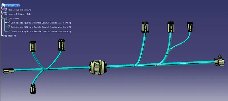
In above slide, i take both assembly of HARNESS A & B in new product file, where i switched workbench in electrical assembly design, with the help of "Connect electrical devices", i interconnect both assemblies together as shown in picture.
---------------------------------------------------------------------------------------------------------------------
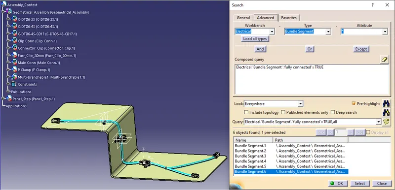
In Above slide, i created one context file and in same product file i created one geometrical assembly file and load all components in it. With help of Panel, i placed all electrical defined connector and clips on decided place. Then switch work bench in electrical harness installation, where i created bundles and connect them with each other.
After all bundles are created, i checked continuity of bundles by using edit command given on top side of work bench, there i select option advance, workbench selected as Electrical, Type selected as bundle segment, attirbute selected as fully connected and query composed with true, and found all bundles are fully connected.
---------------------------------------------------------------------------------------------------------------------
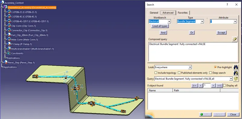
In above slide i checked bundle continuity with False query and found no and bundle having continuity issue.
---------------------------------------------------------------------------------------------------------------------
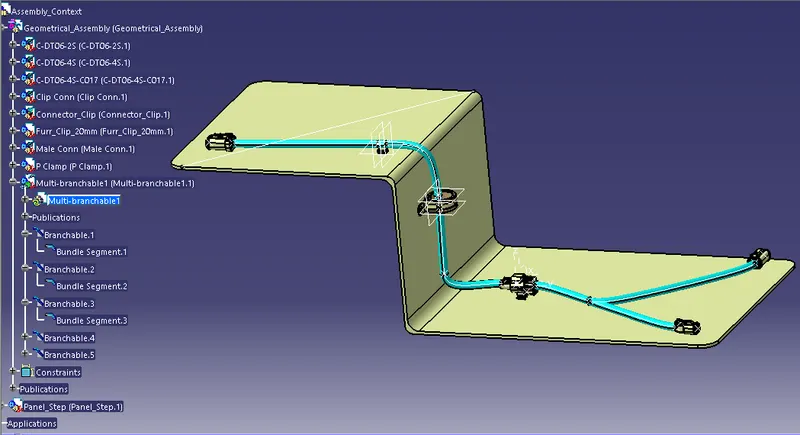
In above slide i checked for Geometrical bundle warning, no any yellow warning shown in bundles due to bundle diameter, bend radius or vector position.
--------------------------------------------------------------------------------------------------------------------
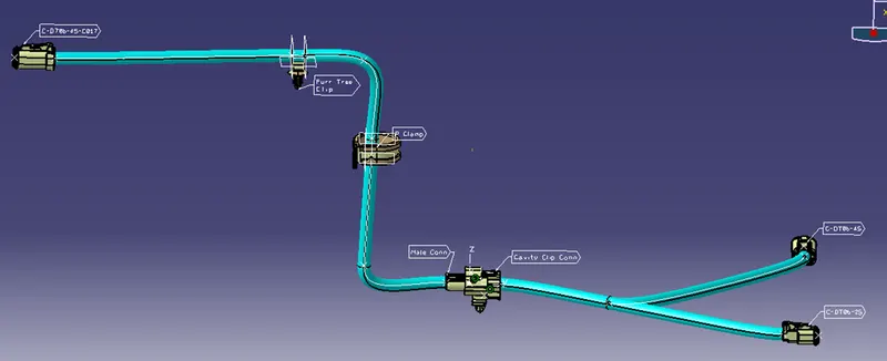
In above slide, i created 3D annotations and named all connectors, for that first i swithed to assembly design workbench, and ensured geometrical bundle is activated. Then i created Plane for annotations and then start ceate annotation connector wise gave names to all connector.
---------------------------------------------------------------------------------------------------------------------