Wiring harness design in CATIA V5 - 3D modeling Week 4 Challenge
|
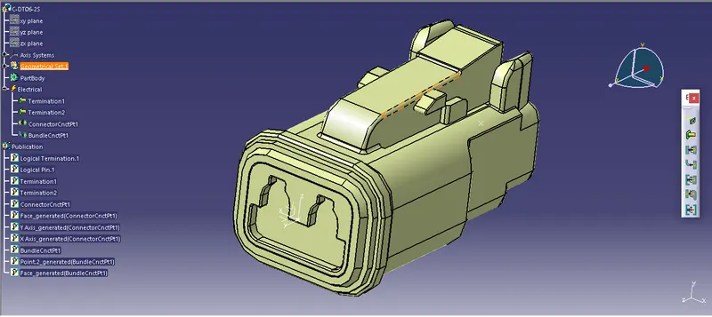
In this slide, 1st in part design workbench connector C-DT06-2S is geometrically defined. 1st creatd center point on mating face of connector and bundle entry face of the connector. In this slide, switched workbench from part design to electrical part design. Define component as a 2 pole connector. Then give property as a connector connector point where representation point is center point of axis system, contact is face side, coincedence is Y axis, orietation is X axis. Then give property as bundle connection point, where Contact is face, point is center point. |
|
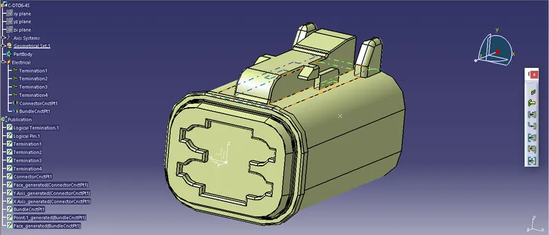
In this slide, 1st in part design workbench connector C-DT06-4S is geometrically defined. 1st creatd center point on mating face of connector and bundle entry face of the connector. In this slide, switched workbench from part design to electrical part design. Define component as a 2 pole connector. Then give property as a connector connector point where representation point is center point of axis system, contact is face side, coincedence is Y axis, orietation is X axis. Then give property as bundle connection point, where Contact is face, point is center point. |
|
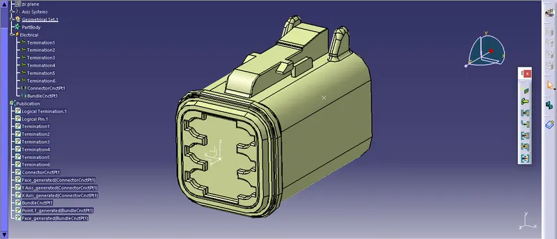
In this slide, 1st in part design workbench connector C-DT06-6S is geometrically defined. 1st creatd center point on mating face of connector and bundle entry face of the connector. In this slide, switched workbench from part design to electrical part design. Define component as a 2 pole connector. Then give property as a connector connector point where representation point is center point of axis system, contact is face side, coincedence is Y axis, orietation is X axis. Then give property as bundle connection point, where Contact is face, point is center point. |
|
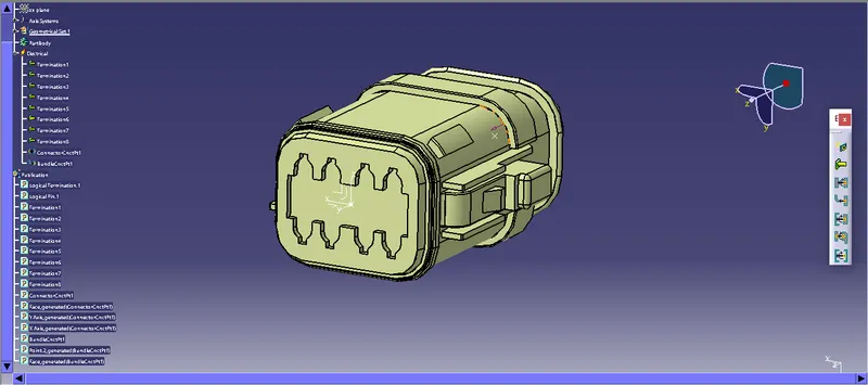
In this slide, 1st in part design workbench connector C-DT06-08SA is geometrically defined. 1st creatd center point on mating face of connector and bundle entry face of the connector. In this slide, switched workbench from part design to electrical part design. Define component as a 2 pole connector. Then give property as a connector connector point where representation point is center point of axis system, contact is face side, coincedence is Y axis, orietation is X axis. Then give property as bundle connection point, where Contact is face, point is center point. |
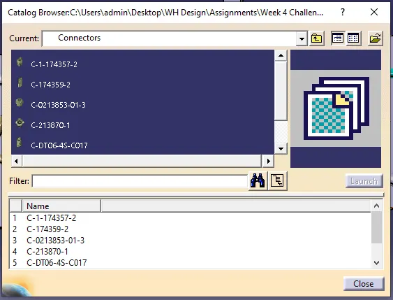
| In this slide, electricaly defined connector is saved via store device command, for that from toolbar, in file, catalog document to be create and select add family then select category as electrical. then save all the electrical connectors in catalg for further easy use. |
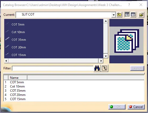
| In this slide, to create catalog for COT TUBE under SLIT COT family, in electrical part design workbench, select command protection part and then select part body, a window will popup for cot tube specification, where we can give properties to cot tube. after creating different sizes cot tube, save it in catalog through store device command, ensure category of cot tube should be conduit. |
|
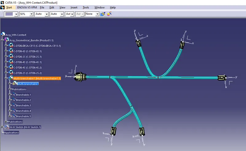
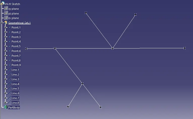
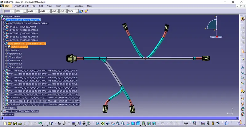
In this slide, 1st i created a prduct file and named "Assy_WH_Context, following with that, in component new product file created and named "Assy_Geometrical_Bundle". Now as assignment given, to prepare a sketch with the given dimensions, i created a pert file sparately and created sketch with help of points and line in Assembly Design workbench.
Then i copy this cat.part file and and paste it in main assembly file. All created file saved in a folder where all related and supporting file to be saved. Now, Assy_Geometrical_Bundle, file opened in seperate window and add all electrically defined components. In Assy_WH_Context, with the help of sketch all components are positioned with help of Manipulation, Snap, Smart Move and compass given in Assembly design workbench. After all components are positioned as per given sketch, workbench switched to Electrical Harness Assembly, then with the help of the command called Geometrical Bundle, assembly file coverted in electically. Then with the help of multibranchable command, bundles are routed from DT06-08SA to DT06-6S, then with help of Add branch point command, bundle splited in 3 parts with a dimension given in assigned sketch. Same done for connector DT06-2S and DT06-4S, after all bundle created, i added protection covering of PVC tape on all bundles and kept 30mm extremity from all connectors. Then i add protection coverings as COT tube on selected bundle as shown in picture.
|
THANKYOU