Wiring harness design in CATIA V5 - 3D modeling Week 7 Challenge
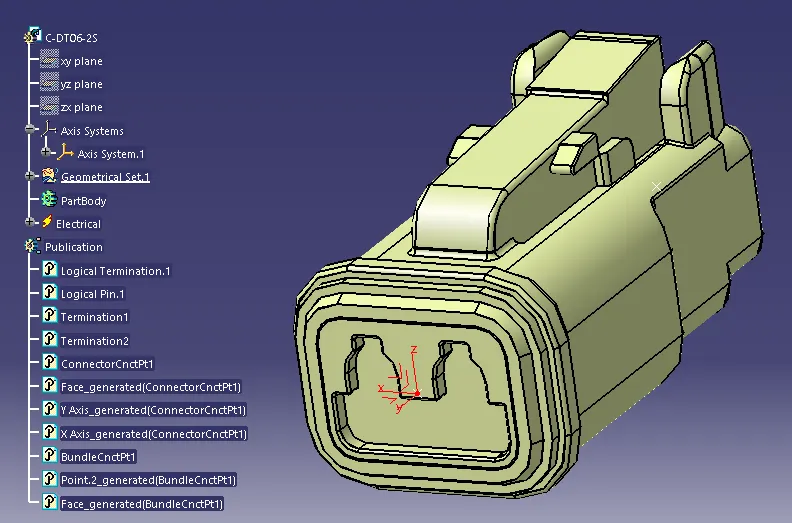
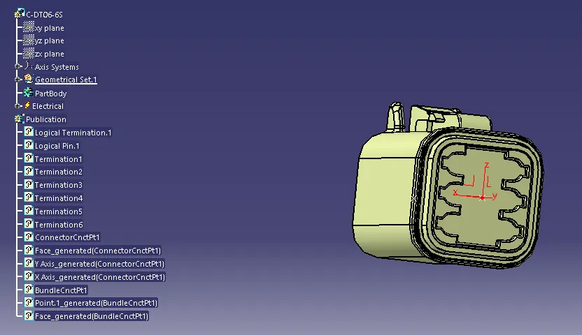
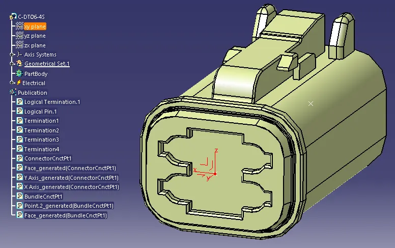
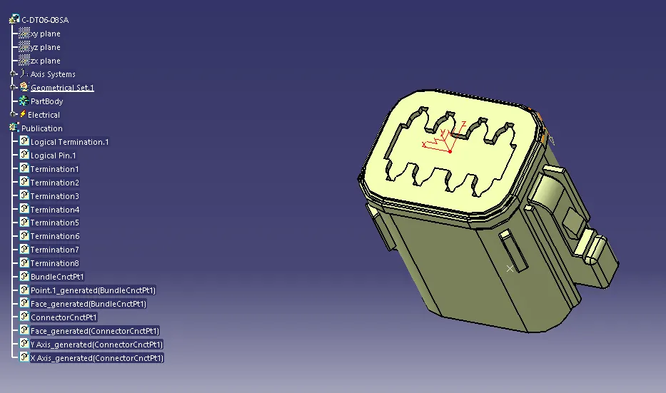
| In above 4 slides, connetor C-DT06-08SA, C-DT06-6S, C-DT06-4S & C-DT06-2S are electrically defined with connector connection point & bundle connection point. | All electrically defined connectors are copied in geometrical bundle product file and positioned as per asked question. | After positioned of all coponents, multibranchable created in Electrical Harness Assembly workbench and then created bundle segments as per sketch created according asked question. | After all budle segments created, protective covering added on bundles. |
-------------------------------------------------------------------------------------------------------------------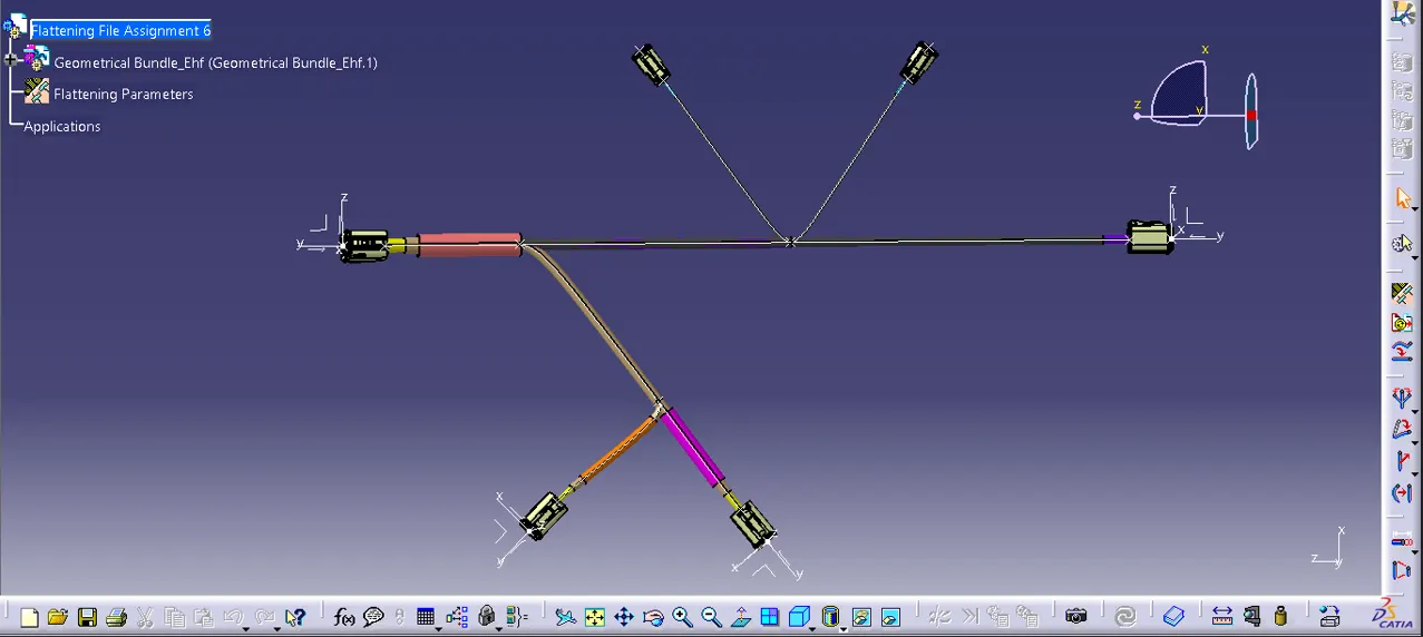
| In above slide geometrical bundle extracted in flattening product file to flatten the wiring harness assembly. |
-------------------------------------------------------------------------------------------------------------------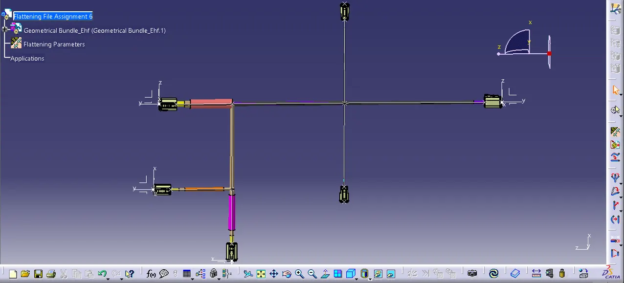
|
In above slide geometrical bundle assembly flatten throug flattening command available in Electrical Harness Flattening workbench. Before falttening of geometrical bundle, falttening parameters given through flattening parameters command. |
-------------------------------------------------------------------------------------------------------------------
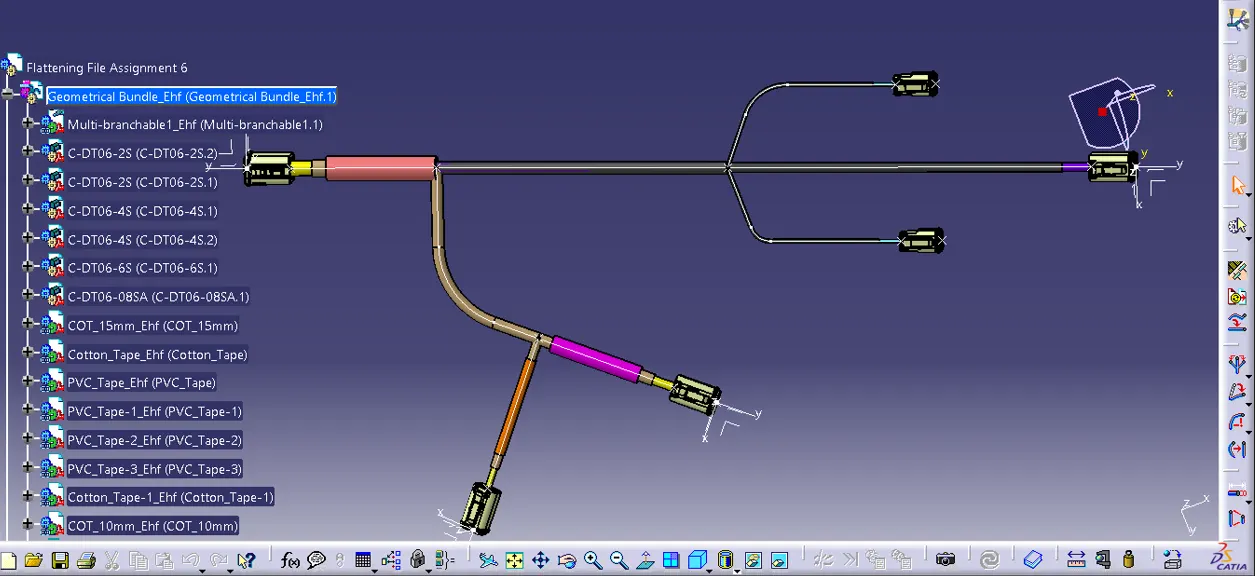
| In above slide, faltten model modofied through rotation, roll, quick roll & straighten command. Also scaling was done for practice purpose. Also linkage checked thorough update flatten link command. |
-------------------------------------------------------------------------------------------------------------------
| After flattening completed of geometrical bundle, i created one drawing file and saved it in desired location. After that selected front view command and selected one face of the connector to get 2D representation of flatten model in drawing sheet. Enabled 3 wireframe to represent all budles as line. |
-------------------------------------------------------------------------------------------------------------------
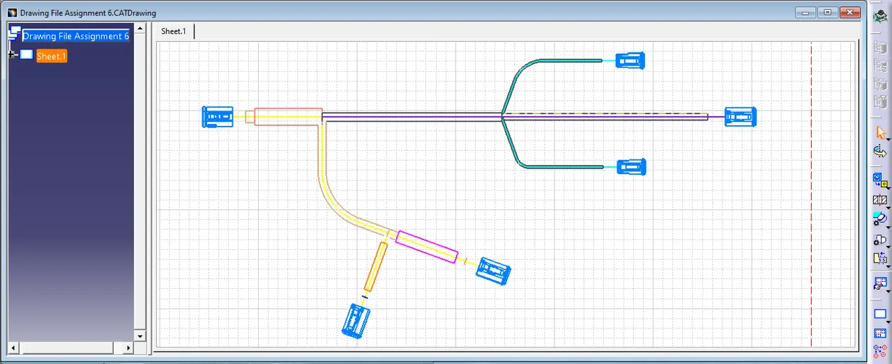
| In above slide i enabled 3D color and 3D spec option in dress up section available in drawing sheet properties. in above slide voilet line shows main trunk protected by PVC tape. And green lines shows branches with PVC tape. In yellow line i considered as heat prone area and protected bundle through 15mm COT and cotton tape. Similarly other two branches protected 1st with COT tubes and then protected by cotton tape. Taping seems not in continuity in 2D representation as there taping over COT protected the bundle. |
-------------------------------------------------------------------------------------------------------------------
THANKYOU