Wiring harness design in CATIA V5 - 3D modeling Week 2 Challenge
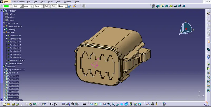
| In this slide, connector C-DT06-08SA is geometrically defined. 1st creatd center point on mating face of connector and bundle entry fce of the connector. Then define axis system on connector mating face wrt connector connection point. Where Y axis is on coincidence side, X axis is on lock side of the connector and Z axis is on the top side of the connector. |
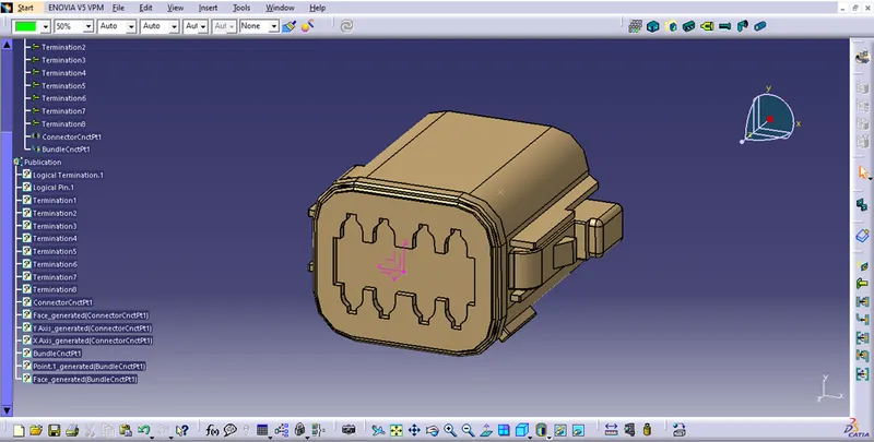
| In this slide, switched workbench from part design to electrical part design. Define component as a 8 pole connector. Then give property as a connector connector point where representation point is center point of axis system, contact is face side, coincedence is Y axis, orietation is X axis. Then give property as bundle connection point, where Contact is face, point is center point. As shown all properties are given and connector is now deinfed as electrical. |
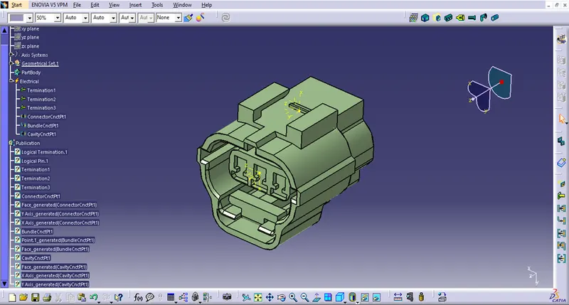
| In this slide, connector C-2-174357-2 is geometrically defined. 1st created center point on mating face of connector and bundle entry face of the connector. Then define axis system on connector mating face wrt connector connection point. Where Y axis is on coincidence side, X axis is on lock side of the connector and Z axis is on the left side of the connector. Similarly in this connector slot given for cavity mounting, so after giving geometry to bundle connection point and connection point, we have to give geometry for cavity connection point where cavity (Clip) wil mount. As per cad mdel I defined a center point and then give axis system as X axis is coincidence axis, Y axis is orientation axis and Z axis is either left or on right side, so keep Z axis on left side. #) Switched workbench from part design to electrical part design. Define component as a 3 pole connector. Then give property as a connector connector point where representation point is center point of axis system, contact is face side, coincidence is Y axis, orientation is X axis. Then give property as bundle connection point, where Contact is face, point is center point. Then give property for cavity connection point where X axis is coincidence axis, Y axis is orientation axis. As shown all properties are given and connector is now defined as electrical. |
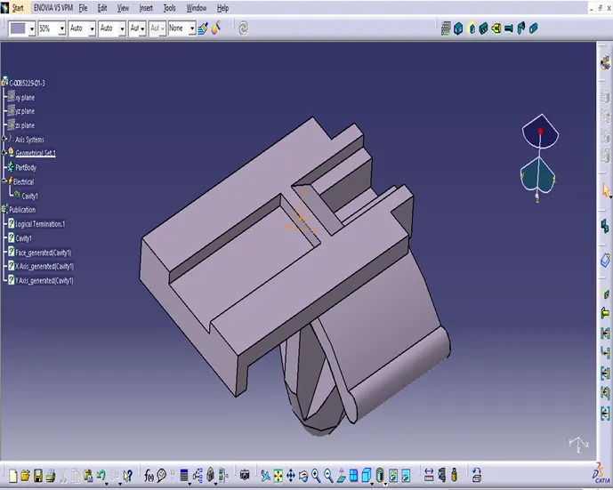
| In this slide, clip C-0085229-01-3 is geometrically defined. Geometry only need to give where clip get lock with the connector. 1st select the middle point of line which will contact connector. Then give axis system as X axis is coincedence axis, Y axis is orientation asix as same as given in connector. Then switch workbenck to electrical and define component as Mounting Equipment and the define component as cavity.And give property for cavity as X axis is coincendece and Y axis is orientation. |