Wiring harness routing & packaging Rules Week 3 Challenge
Ans.1 For Q-1:
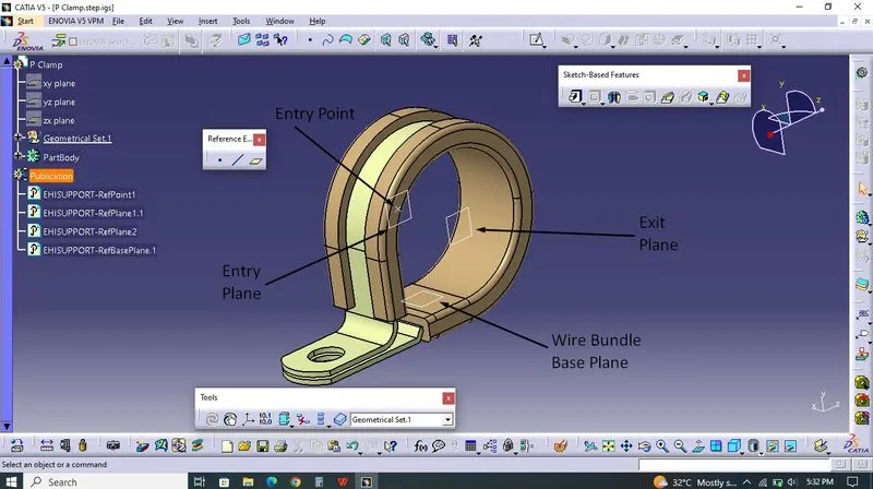 File opened at Part design Workbench and created Point for Wire bundle entry, created Plane using that point for Wire bundle entry. Created Point and Plane at opposite side for Exit for Bundle. Created Plane for Base Plane of Wire bundle.
 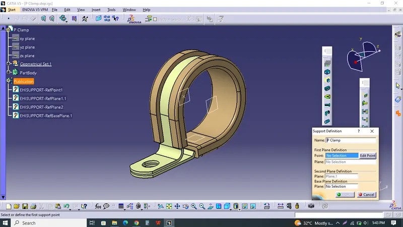 Switched to Electrical Part Design, Selected Support for assign Electrical definition of P-Clamp. Selecting Point & Plane for Entry - Selecting Plane for Second definition - Selecting Plane for Third definition for Bundle Base. then ok.
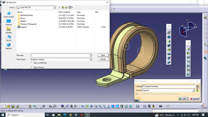 After that, I created Catalogue for Support component. Added P clamp into the Support Catalogue.
Ans.2 For Q-2:
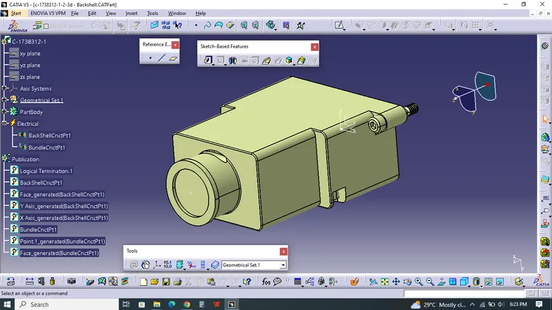 File opened at CATIA V5. At Part Design Workbench, Created Point for Bundle Entry at Backside. Created Point & Axis for Backshell Connection Point.
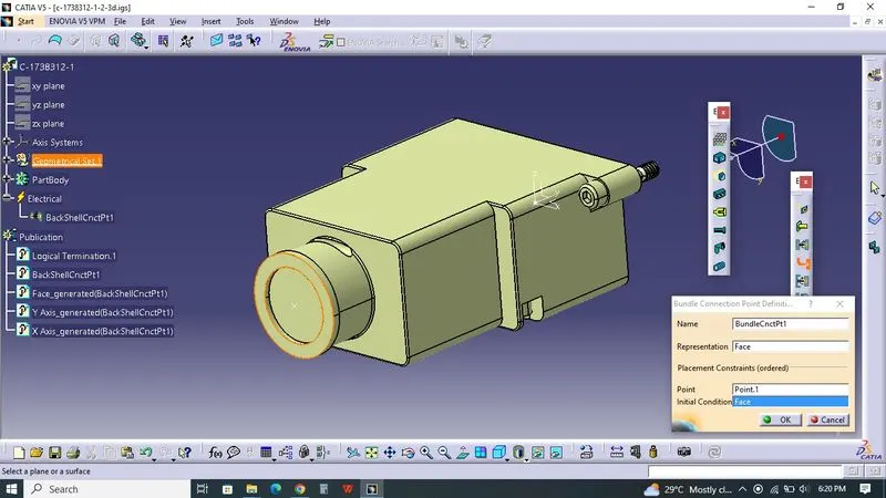 Switched to Electrical Part Design Workbench, Part defined as BackShell. After Backside of Part, Point defined as Bundle Connection Definition.
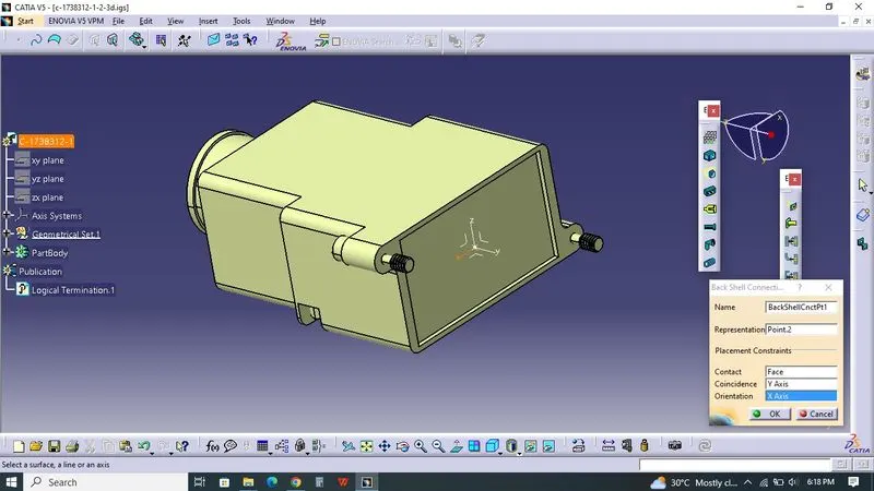 At Backshell Connection Definition, Part is Selected at First. And Point is selected as a Representantion, Face as a contact, Y Axis as a Coincidence, X Axis as Orientation, Then ok.
Ans.3 For Q-3:
At Earlier Stage, Catalogue created for Corrugated Tubes. Family added in Catalogue which was named as Slit COT.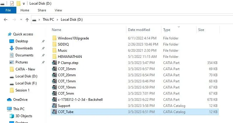 After that, Entered into Electrical Part design, Select Define Protective Part, then Selected Plane Window would pop-up. Then entered ID Value, Thickness, Bend Radius, Finally ok.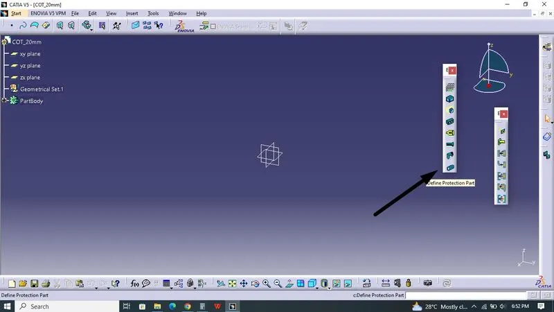
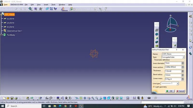 Part saved at First. After that only We can save Store device Command. Added the Part we created by selecting COT_Tube Catalogue and added into Slit COT family.