Wiring harness design in CATIA V5 - 3D modeling Week 4 Challenge
All Hareness components were Downloaded as per question. At Part design Workbench, Point & Axis created at Each Components Back & Front side Respectively. At Electrical Part Design Workbench, Each Component were defined by Connectors. Points at the Connectors Back side defined by Bundle Connection Point. Axis at Connectors Front side defined by Connector Connection Point. After all the connectors were saved in Connectors Catalogue.

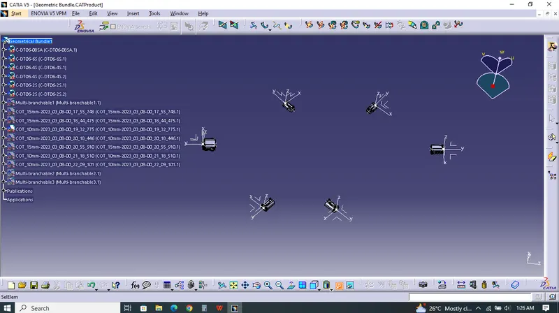
 I created Product which named as Geometric Bundle Assembly. Using Catalogue Browser. Connectors imported into it. Each were placed based on question.
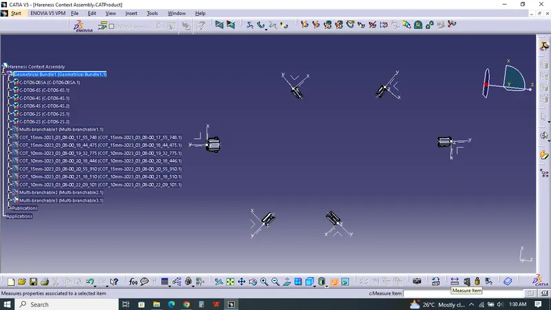
I created Product named as Hareness Context Assembly and imported Geometric Bundle Assembly. By selected Geometric Bundle to Activate Hareness.
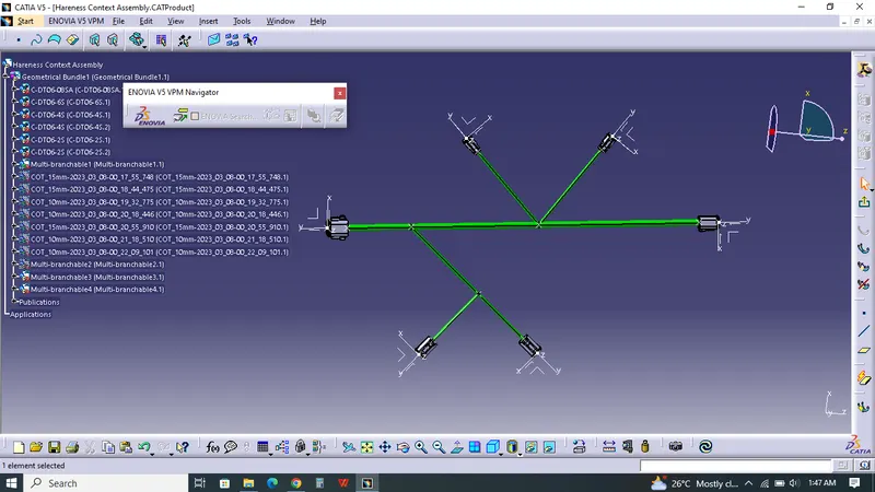
 By using Multi Branchable Document, 08sa & 06s Connectors connected with 10mm Diameter, Bending Radius entered and Route definition used to create the bundle between them which I considered as Main Branch. Using Add Branch Point Main Bundle splitted into three Parts which is 100mm,200mm,250mm. Bottom Side, two numbers of 04s Connectors placed as per Question using Axis Rotation, Snap,Manipulation. From 100mm Main branch, one 04s Connector connected which has 250mm length and 5mm Diameter by using Branch definition Command. This Sub Branch spiltted into two parts which is 100mm from Connectors. Another 04s Connector connected which is 100mm from Sub branch. At top side, two numbers of 02s Connector were placed as per question and were connected individually from Second Branch point of Main Branch which are 150mm length and 5mm Diameter.
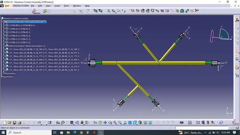
 After Protective Covering Tube added by using Protective Covering Command. Window poped up. I used the Slit Cot Catalogue which was created at previous challenge. Browsed the Catalogue and selecting the COT 15mm for Main Branch Protective Cover and COT 10mm for Sub-branch Protective Cover. Protective Cover extremity were 30mm away from each Connectors.