Wiring harness design in CATIA V5 - 3D modeling Week 2 Challenge
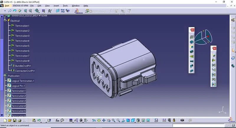
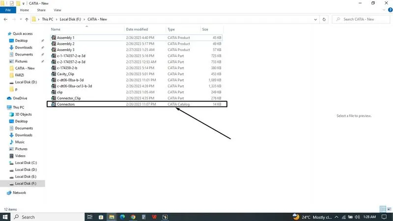 Open the file from CATIA, Then I saved it. Before that, I created Catalogue File for Connectors. I saved the connectors into Connectors Catalogue. In Part Design Workbench, I created Point at Bundle side for Bundle connection point& Created point for Axis which help to Connector connection point. In Electrical Part Design Workbench, I defined the DT06-08SA as Connector, then I select Connector connection point, After that clicking Part first, Window poped up,selecting point as representation,selecting face as contact, X axis as Orientation, Y axis as coincide,Finally ok. At BackSide,defined the Bundle Connection Point, After that clicking Part first, Window poped up,selecting Face as representation, selecting point as point,selecting face as Initial Condition.
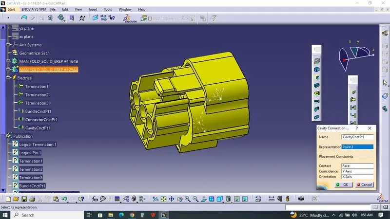
 Open the file from CATIA, Then I saved it. I saved the Female connectors into Connectors Catalogue. In Part Design Workbench, I created Point at Bundle side for Bundle connection point& Created point for Axis which help to Connector connection point. In Electrical Part Design Workbench, I defined the Tyco 174357-2 as Connector, then I select Connector connection point, After that clicking Part first, Window poped up,selecting point as representation,selecting face as contact, X axis as Orientation, Y axis as coincide,Finally ok. At BackSide,defined the Bundle Connection Point, After that clicking Part first, Window poped up,selecting Face as representation, selecting point as point,selecting face as Initial Condition. I select Cavity connection point, After that clicking Part first, Window poped up, At Bottom Side of Connectors, selecting point as representation, selecting face as contact, X axis as Orientation, Y axis as coincide,Finally ok.
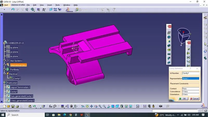
 Open the file at CATIA, save the file as Clip. Create the Point and Axis for Cavity Connection point at Part design workbench. At Electrical Part design workbench, Select part as Mounting Equipment, then Selecting Cavity, Select point as Representation, Face as Contact, X axis as Orientation, Y axis as coincide,Finally ok.
  Inserting Electrical Assembly Design, Paste all Components, select Electrical Device, Then select Connector & Clip,those were mated together. select Electrical Device, Then select Connector & Female Connecctor,those were mated together.
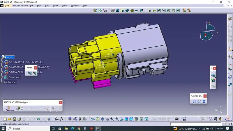 Connector and Female connector doesn't match. but i used your input, followed rules and mated together.