Wiring harness routing & packaging Rules Week 3 Challenge
Aim: Define Clamps, backshells, and corrugated tubes with all their necessary electrical properties using Electric Part Design Workbench in CATIA V5.
Objective:
- Download required clip cad data & define it as Electrical support using an Electrical Part Design Workbench. Define all the necessary properties.
Steps:
- Download the P Clamp.igs file.
- Define the required geometry parameters (points and entry, exit, base plane) for the Clip.
- Define part as support in the electrical part design workbench.
- For clips, there are two entry and exit points so we have to define the clip twice to accommodate it.
- Download required Backshell data & define it as Electrical support using Electrical Part Design Workbench. Define all the necessary properties.
Steps:
- Download the backshell TYCO-1738312-1 from TE.com
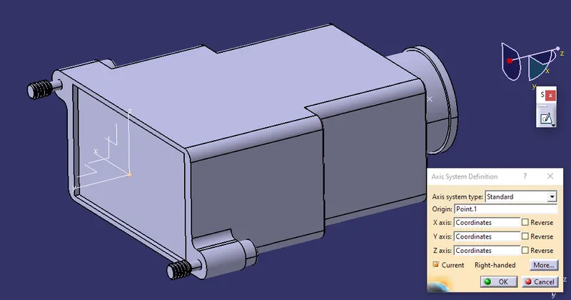
- Define geometry parameters for backshell.
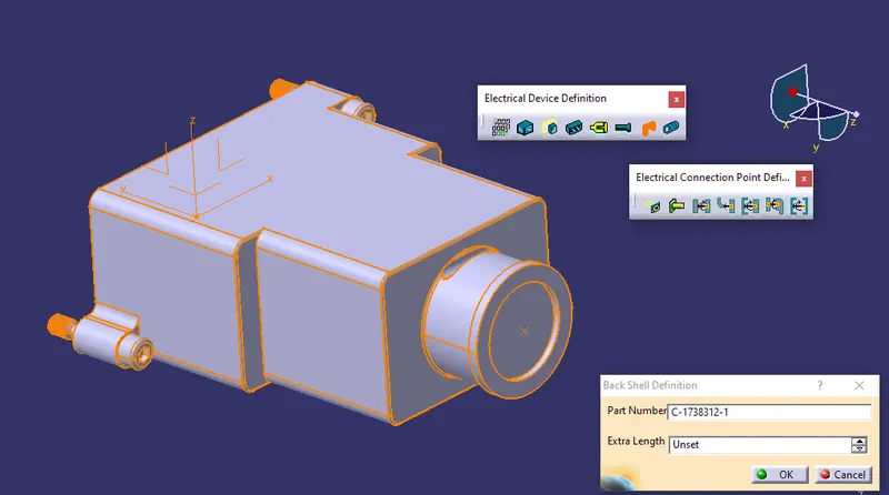
- Define part as backshell.
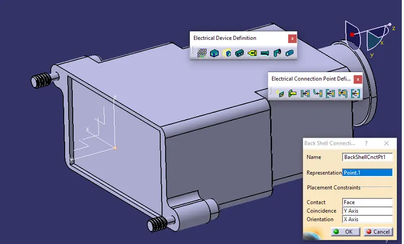
- Define the Backshell Connection point.
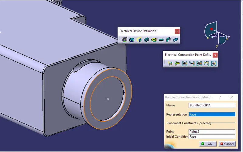
- Define the Bundle Connection point.
- Create the Following Corrugated tubes & Add them to the Catalogue under the “Slit COT” family.
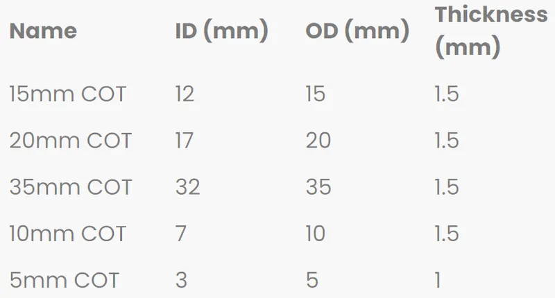
Steps:
- As there is no file to download for corrugated tubes we have to make each type of corrugated tube and them into a catalog so they can be used at a later stage.
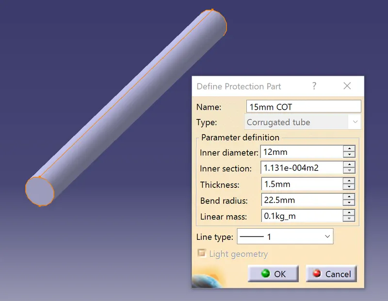
- In the electric part design workbench, define the protection part, and give the necessary dimensions for the COT tube. Give values for inner diameter and thickness.
- Create a COT tube catalog.
- Give a name to the catalog and define its type as “conduit”. For insulation tape type is “electrical”.
- Define part family name.
- Save the “Slit COT” catalog.
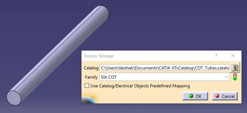
- Add all the created Corrugated tubes to the catalog individually.
Solution:
P Clamp
STEP 1: DEFINING GEOMETRY PARAMETERS FOR THE CLIP
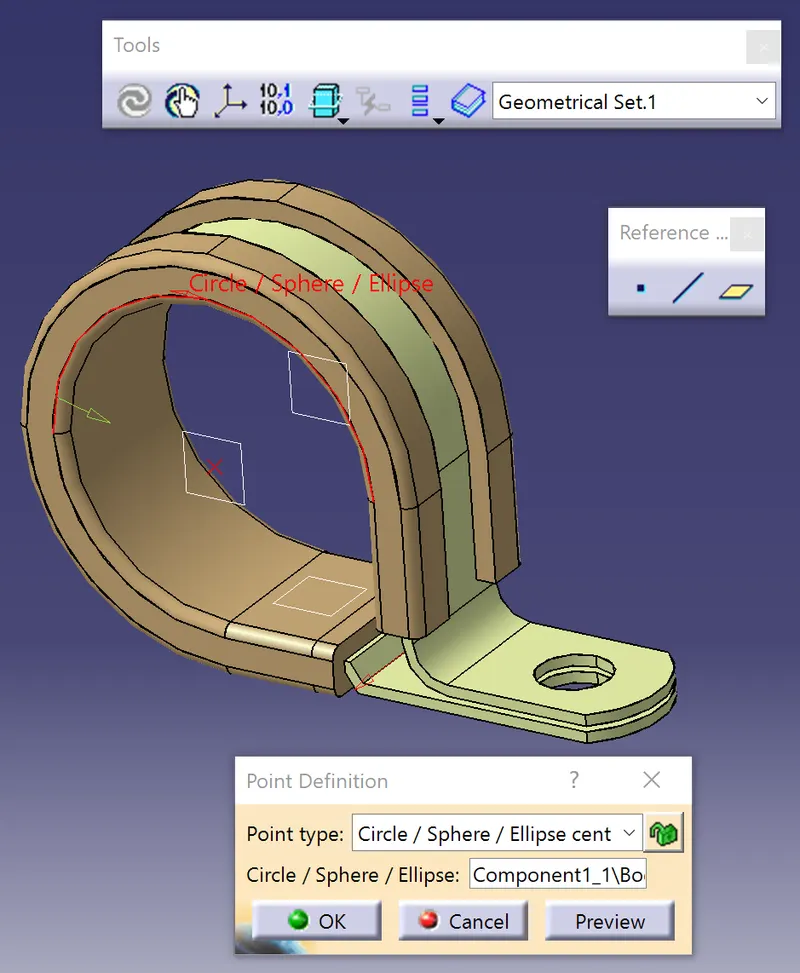
STEP2: DEFINE ENTRY, EXIT, AND BASE POINT AND PLANES FROM THE FIRST SIDE
STEP3: DEFINE ENTRY, EXIT, AND BASE POINT AND PLANES FROM THE SECOND SIDE
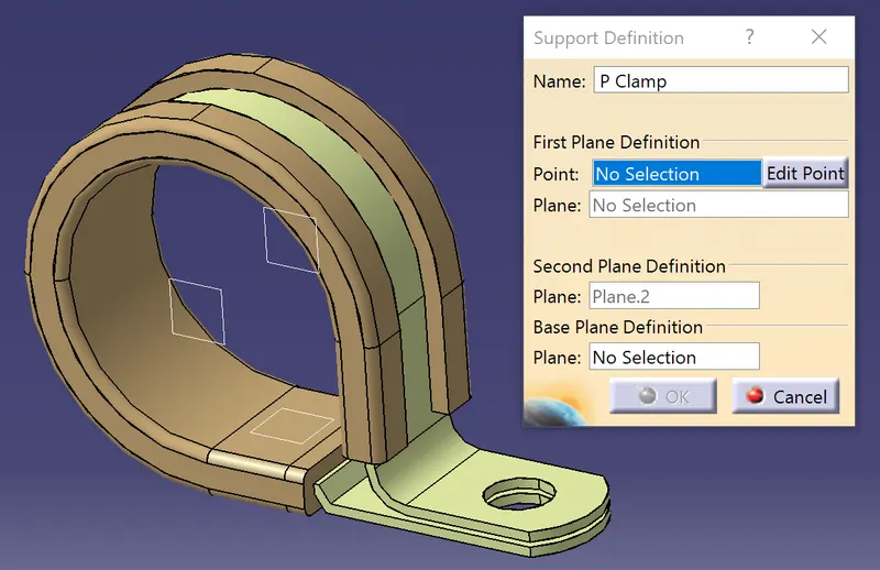
STEP4: COMPLETELY ELECTRICALLY DEFINED P-CLIP
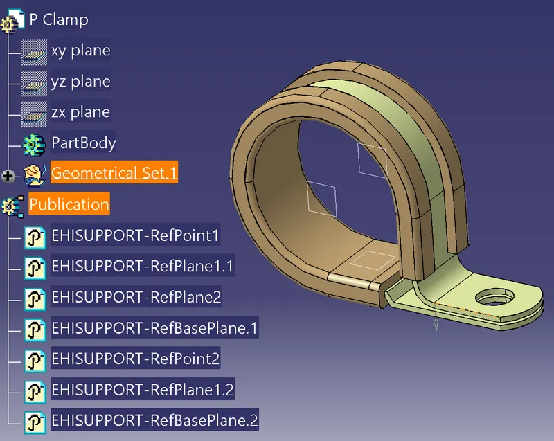
BACKSHELL TYCO-1738312-1
STEP1: DEFINE GEOMETRIC PARAMETERS FOR THE BACKSHELL
STEP2: DEFINE PART AS BACKSHELL
STEP3: DEFINE BACKSHELL CONNECTION POINT
STEP4: DEFINE BUNDLE CONNECTION POINT
CORRUGATED TUBES
There are five types of corrugated tubes to be made. For now, the steps are shown for the 15mm COT tube. The same steps have to be followed while creating the other COT tubes.
STEP1: DEFINE THE PROTECTION PART IN THE ELECTRICAL PART DESIGN WORKBENCH, GIVE VALUES FOR I.D., THICKNESS, AND BEND RADIUS
STEP2: DEFINE COT TUBE CATALOG
STEP3: GIVE NAME AND TYPE FOR CATALOG
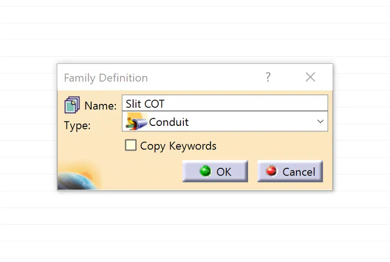
STEP4: GIVE PART FAMILY NAME
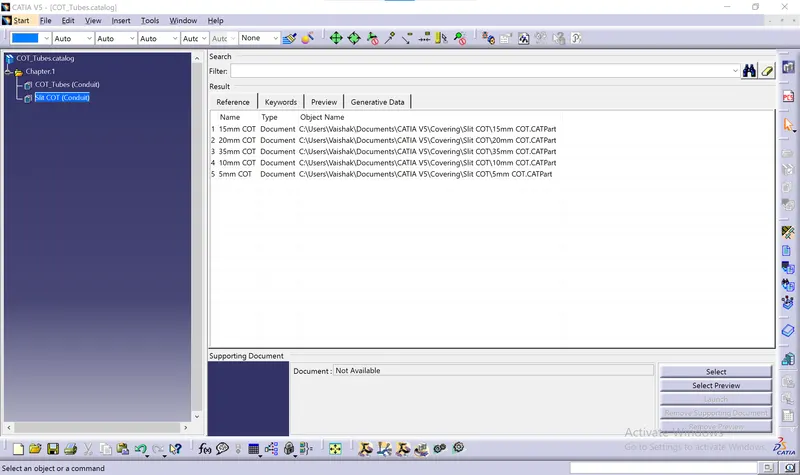
STEP5: SAVE CATALOG WITH NAME “Slit COT”
STEP6: ADD 15mm COT TUBE IN CREATED “Slit COT” CATALOG
CONCLUSION:
Using the CATIA V5 electric part design workbench, the provided clip, backshell, and COT tubes were fully described with all of their geometrical and electrical characteristics.
REFERENCE:
- P Clamp (https://drive.google.com/file/d/1cL9NiCnMl1I0SGlRESUZwdjSP5_9eAlb/view)
- Tyco 1738312-1 (https://www.te.com/usa-en/product-1738312-1.html)