Wiring harness design in CATIA V5 - 3D modeling Week 7 Challenge
Aim:
To create flatten view of the previously prepared Electrical harness assembly in Catia V5.
Objective:
- Flatten the harness assembly prepared in week 4 challenge.
- Place the flattened view on drawing sheet.
- To add the protective covering and enusre that it is of different colour in drawing.
Procedure:
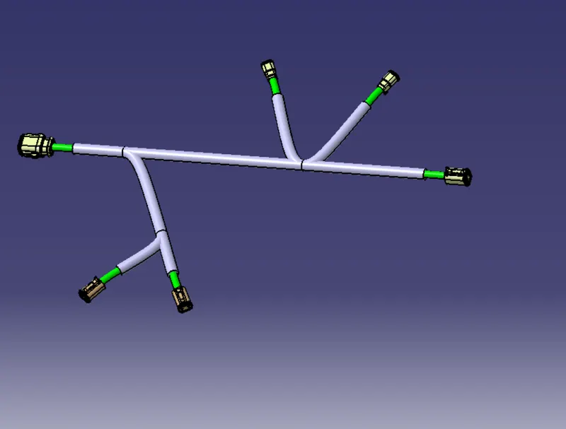
- Open the assembly model already created in Catia V5.
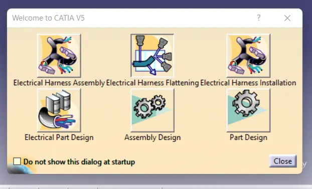
- Now open new product file and select Eletrical harness flattening workbench.
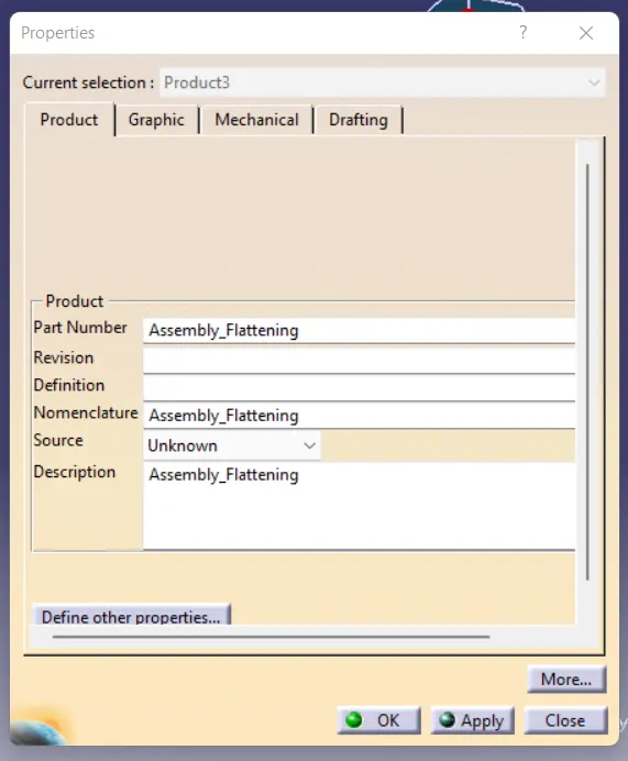
- Rename the product file name as required as shown below.
- Now adjust both the file window equally as shown below:
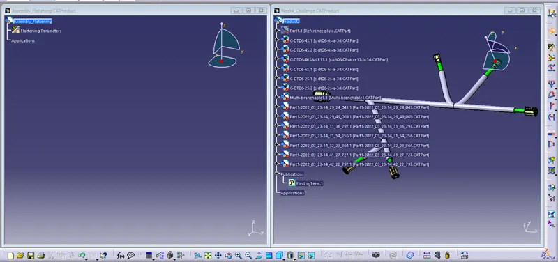
- Bring the harness assemble in the flattening product file using extract option
 .
. - After the assmebly is extracted the file type is changed to .EHF (which stands for electrical harness assembly flattening) as shown in below image.
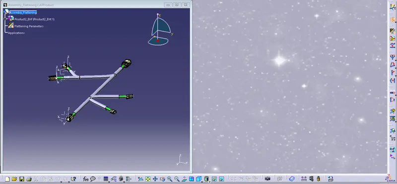
(Now we have to flatten the assemby)
- Select flatten option
 .
. - Then select all the electrical bundles which has to be flatten as shown below.
- One can also select one main bundle branch and then click Select all branches in the flatten window.
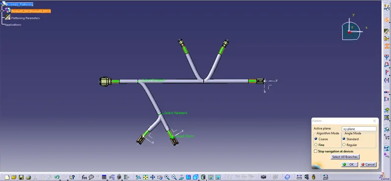
- After flattening the bundles will look as below.
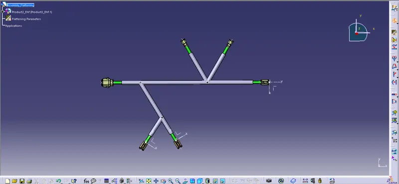
Here we can select either XY plane as the flattening plane or any respective flat surface of the any one connector.
Since here the flattening is done on there positions automatically, we can directly go to the drwing part.
But this wont happen always. When the branches are not orient as per required flattening, we have to adjust the branches such that all the branches are their in their respective places and orientation.
Let see how to adjust the orientation of the branches if required.
- To adjust the branch angle click on rotate option
 .
. - Now select the branch to be rotated.
- Give the angle as required to bring the branch on the respective place.
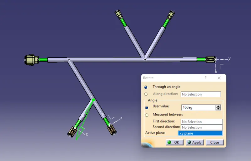
- This step can be performed for all the other sub - branches if required.
- Since we have flatten and oriented the assemble properly to their respective places and orientation as required, next step is to create the drawing view.
- Before that change the parameter as shown below.
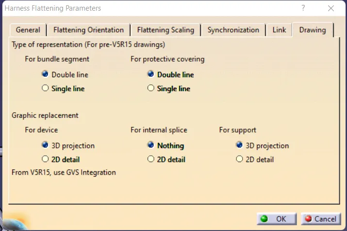
- Open new drawing file and set the following parameters as shown in figure.
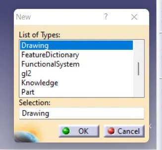
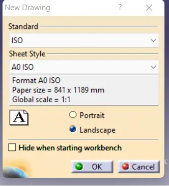
- First save the drawing file as Assembly_Flattening.
- Adjust both the windows side by side for better unerstanding.
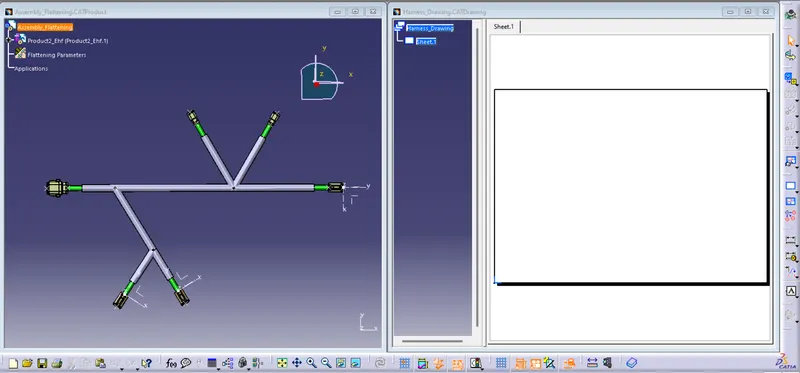
- Click front view option
 in the drawing file and then select any one flatten surface of the assembly.
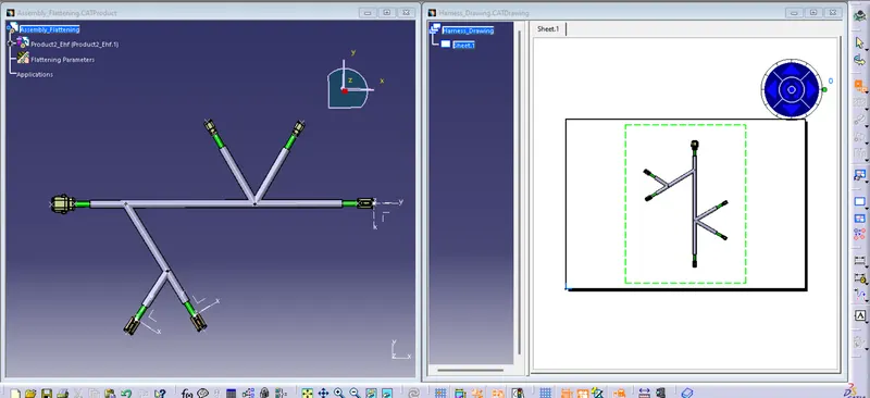
- Adjust the view with the help of the manipulation tool
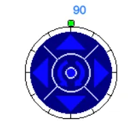 as required..
 - Once the view is oriented, click the drawing sheet to complete.
- Now we have to change some parameters so that we get the drawing as required.
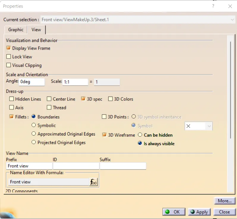
- Right click on the view and select properties and properties window will open.
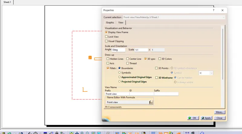
- Under view tab click on the 3D wireframe option and make it visible always.
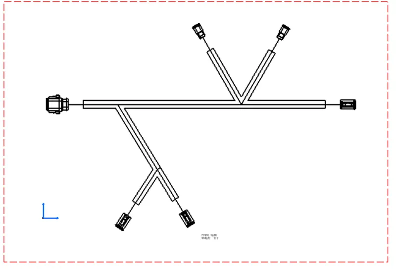
Conclusion:
The Flattened view and the flattened drawing of the Electrical harness assemlby is created. The bundle protectioncs are shown in different visual comapred to the bundle branches.
Thank You.