Wiring harness design in CATIA V5 - 3D modeling Week 7 Challenge
AIM- To prepare a flattened-view of a previously created harness assembly
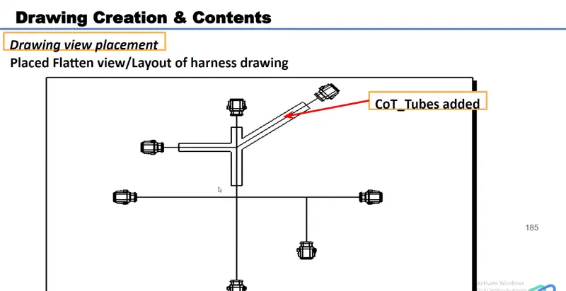
OBJECTIVE- The objective of this project is to create a flattened-view for a harness assembly and then place it on the drawing sheet. It is desired that the bundles with protective coverings are represented with different visuals on the drawing sheet.
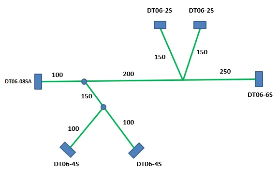
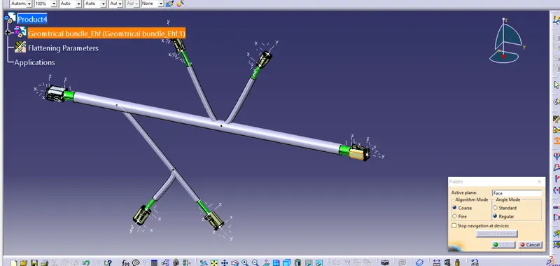
FIGURE1: PREVIOUSLY ROUTED HARNESS ASSEMBLY FOR WHICH FLATTENED-VIEW HAVE TO BE CREATED
To make a flattened view of any wiring harness we should be working in the Electrical Harness Flattening workbench of CATIA V5. We should make sure that the flattening file should be in the same folder where you have all the parts of the harness assembly.
CONTENT-
The following steps are to be done to complete this project.
STEP1- Defining Harness Flattening parameters
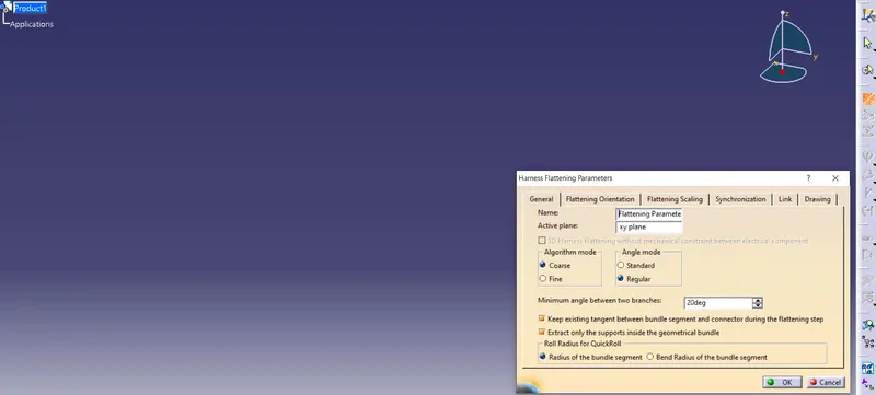
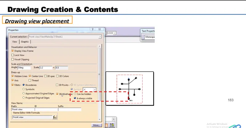
First, we should make a new product file inside the Electrical Harness Flattening workbench. Second, we should define the harness flattening parameters by clicking on its icon as shown above. In the general tab, we should select the settings as shown above. After the general tab settings are complete we should define the settings for the drawing tab as shown below.
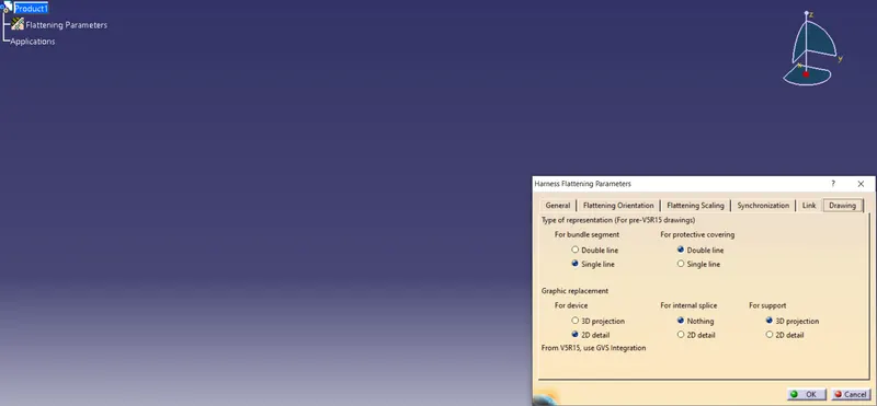
It should be noticed that the type of representation for the bundle segment and protective covering are different from each other. Also for devices, "3D projection" can be used if the connectors are added to the electrical drawing catalog.
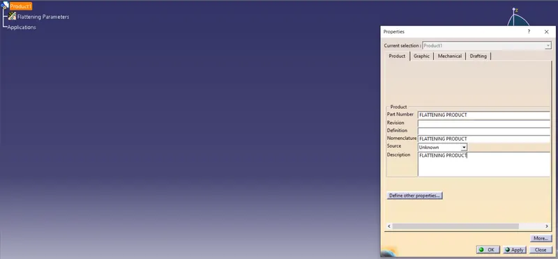
STEP 2- Rename the product file as the Flattening Product.
STEP 3- Bring the harness assembly into the newly created Flattening Product by using the "Extract" feature.
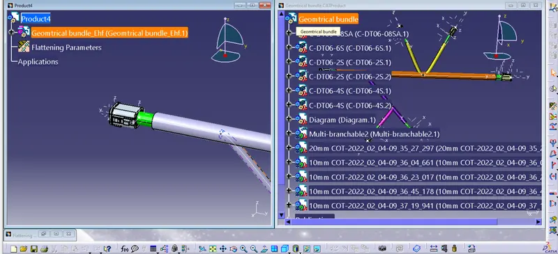
Using Flatten command Flatten the Product
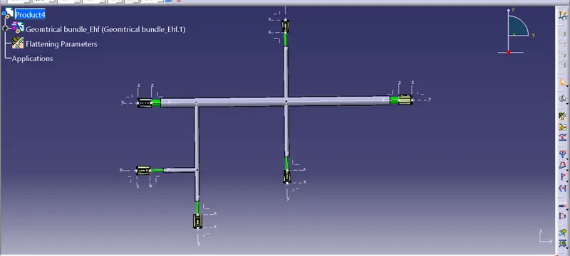
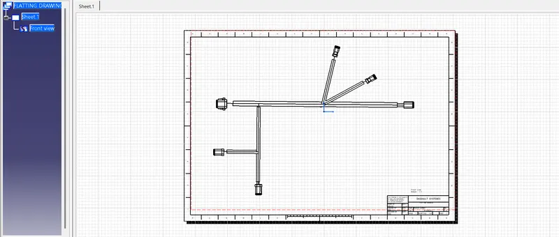
Create a Drawing