Wiring harness design in CATIA V5 - 3D modeling Week 5 & 6 Challenge
Aim: To route the Wiring Harness in the Electrical Workbench as shown in the given image as Harness A & B and inter connect them as the single harness assembly with proper annotations to the Connectors. Creation of CATPart and converting into IGS format
Connector Definition:
- Firstly, the Connector 3D part file are downloaded from the resource
- Next step is to define the Geometrical parameters of the connectors. The required geometrical parameters are as follows
i) Connector Connection Point: This point is used for the connection of one connector to the another connector.
ii) Harness Bundle Entry point: This point defines where the harness bundle segment point will end when routed to the electrical connector.
iii) Cavity Connection Point: This point is used to define the connection of a connector to a connector clip. This only applies to the connector which have the mounting feature for a connector clip.
Connector Definition in CATIA V5
- For creating Connector Connection point, create a point on the contact face which will be normal to the wire bundle insertion.
- Next create an axis system with respect to the point which we have created and defining the axis direction such that the X-axis should be pointing towards the locking mechanism of the connector, the Y-axis should be pointing towards the front face of the connector adn the Z-axis should be pointing across the connector from left to right.
- Further create a bundle connection point on the midpoint of the face.
- Next, switch to the " Electrical Part Design " workbench
- Define the part as the connector using Define Connector Command and along with it give the number of terminations in the connector.
- Using the Bundle Connection point command define the bundle connection point by selecting the appropriate face and point.
- Using Connector connection point command define the connector connection point by selecting the appropriate face and point along with it slecting the Y-axis as the coincidence and the X-axis as the orientation.
- Same procedure is followed for all the connector to define them electrically.
- Finally, store all the Connectors in the Catalog document
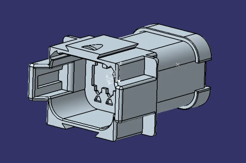
Figure: Connector 1(A)
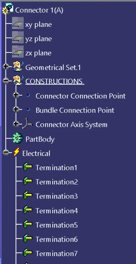
Figure: Expanded Tree(1)
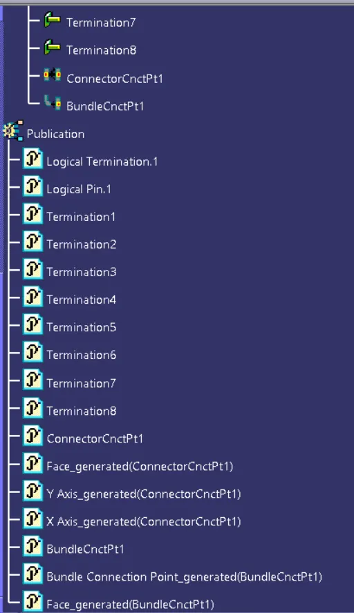
Figure: Expanded Tree (2)
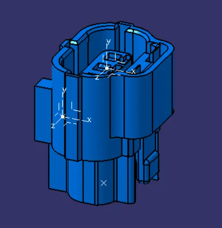
Figure: Connector 2(A)
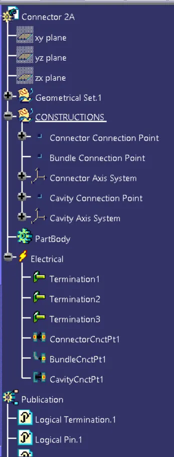
Figure: Expanded Tree(1)
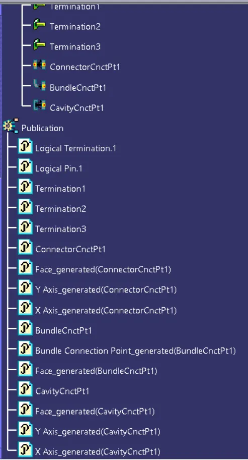
Figure: Expanded Tree (2)
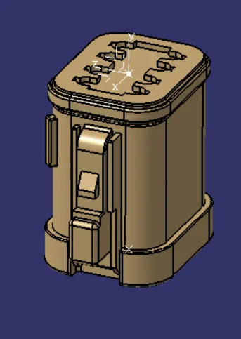
Figure: Connector 3(A)
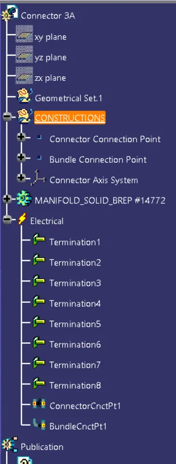
Figure: Expanded Tree (1)
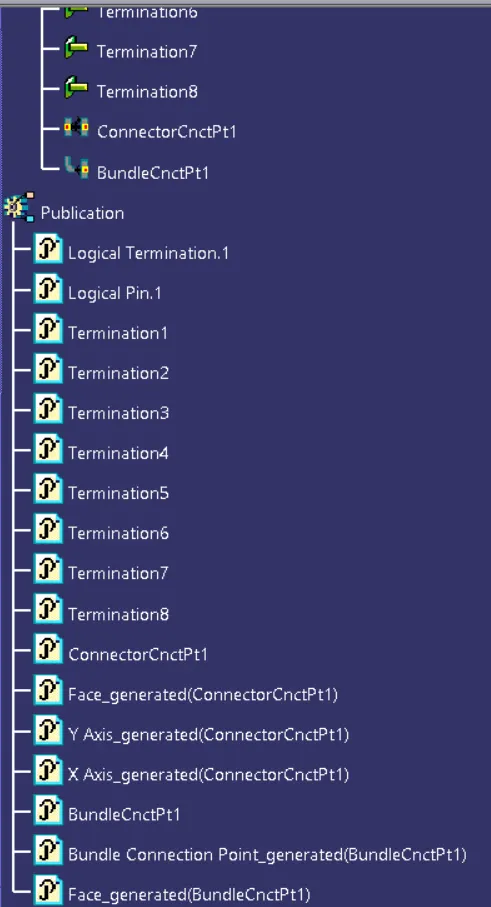
Figure: Expanded Tree (2)
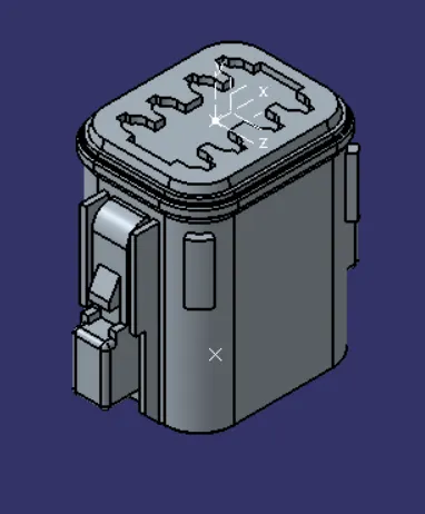
Figure: Connector 4(A)
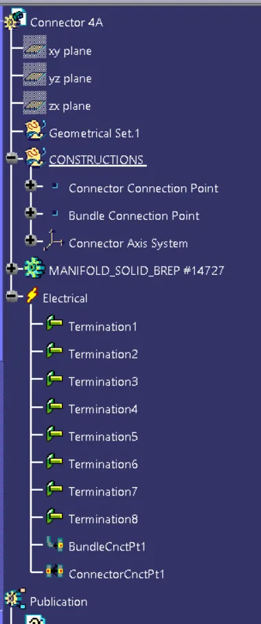
Figure: Expanded Tree (1)
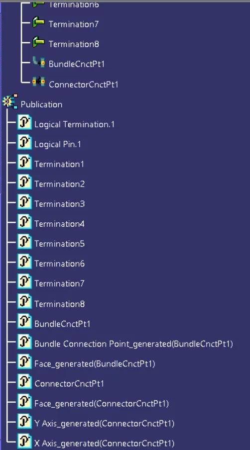
Figure: Expanded Tree (2)
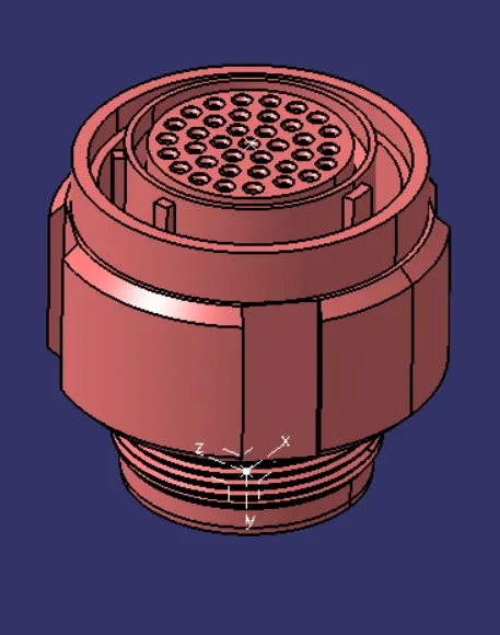
Figure: Connector 5(A)
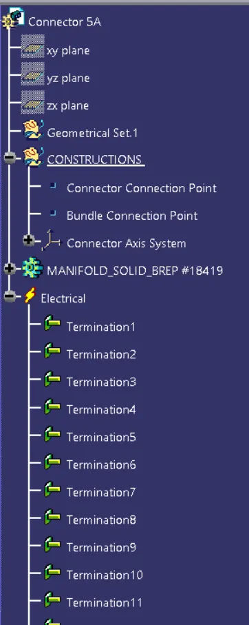
Figure: Expanded Tree (1)
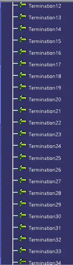
Figure: Expanded Tree (2)
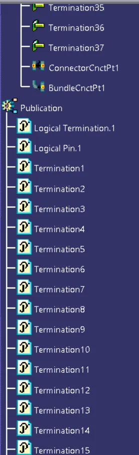
Figure: Expanded Tree (3)
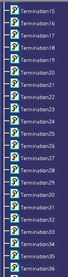
Figure: Expanded Tree (5)
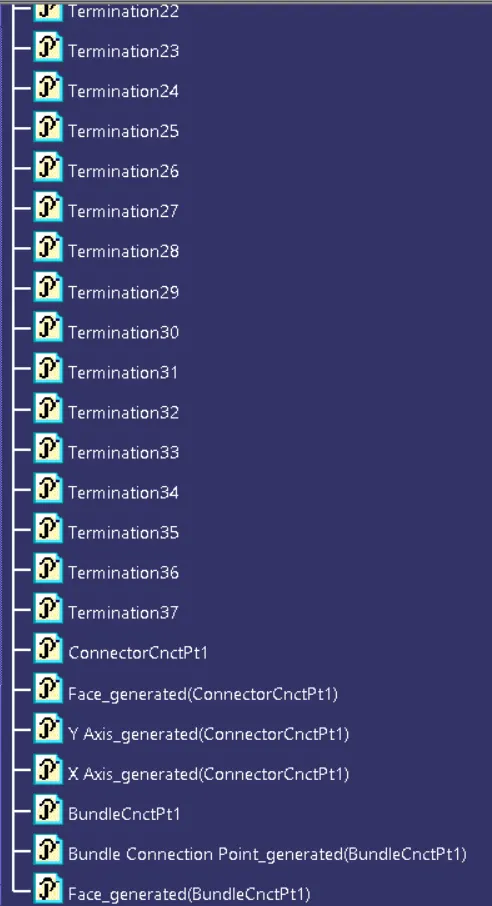
Figure: Expanded Tree (6)
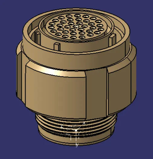
Figure: Connector 1(B)
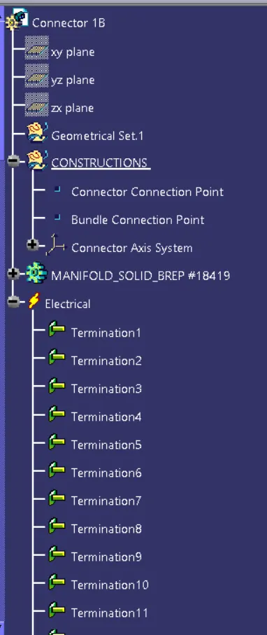
Figure: Expanded Tree (1)
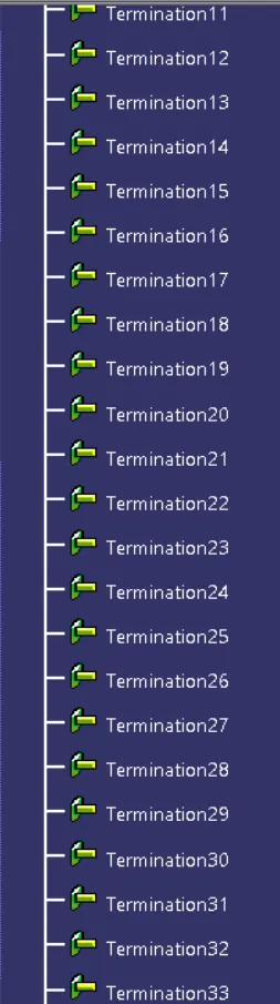
Figure: Expanded Tree (2)
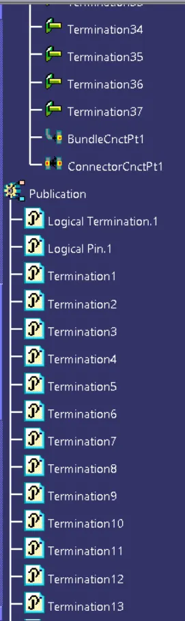
Figure: Expanded Tree (3)
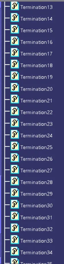
Figure: Expanded Tree (4)
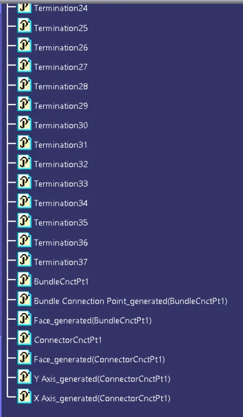
Figure: Expanded Tree (5)
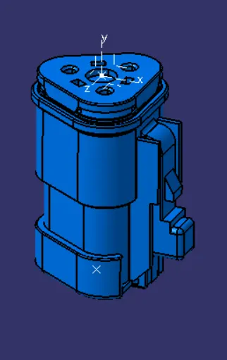
Figure: Connector 2(B)
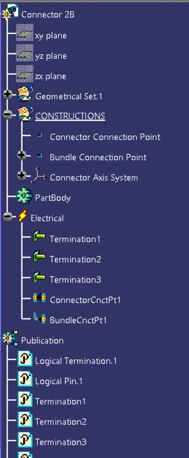
Figure: Expanded Tree (1)
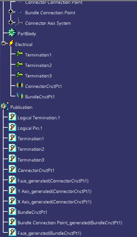
Figure: Expanded Tree (2)
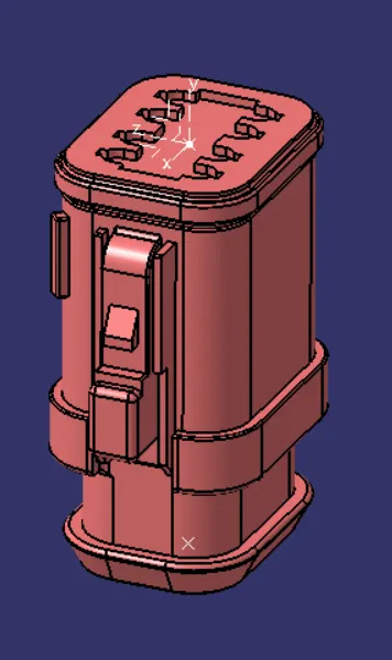
Figure: Connector 3(B)
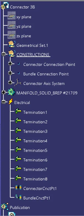
Figure: Expanded Tree (1)
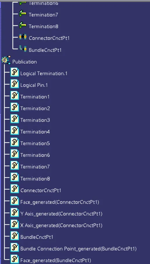
Figure: Expanded Tree (2)
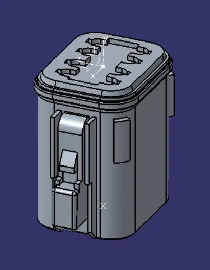
Figure: Connector 4(B)
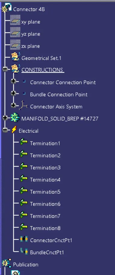
Figure: Expanded Tree (1)
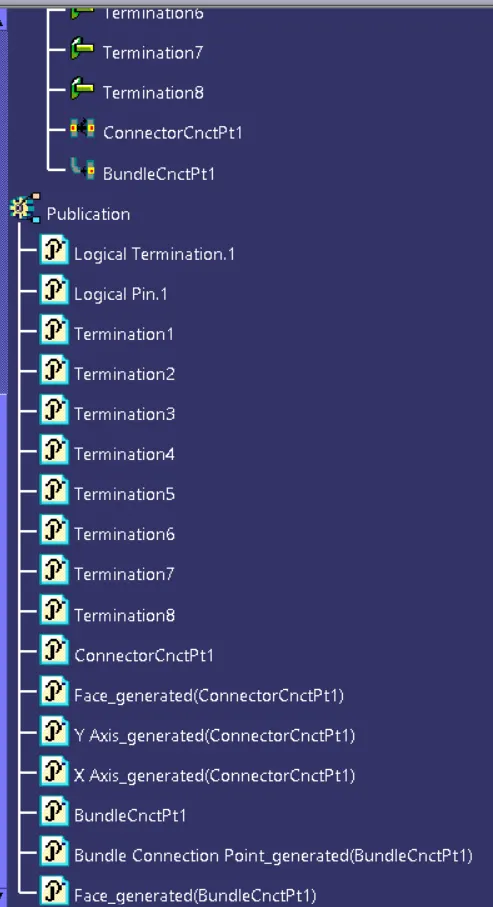
Figure: Expanded Tree (2)
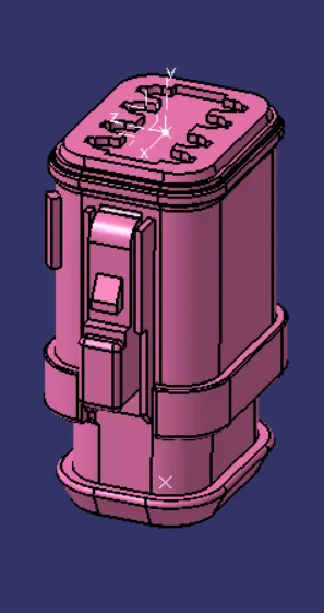
Figure: Connector 5(B)
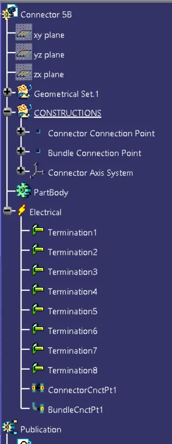
Figure: Expanded Tree (1)
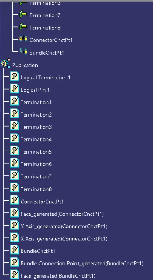
Figure: Expanded Tree (2)
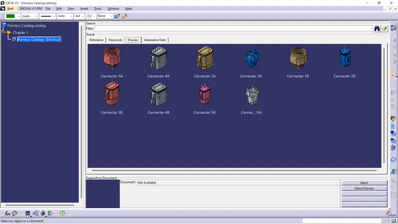
Figure: Connectors stored in Catalog document
After defining the componenets of Wiring Harness next we must prepare the Product assembly for the given harness.
Wiring Harness Product Assembly
Wiring Harness Product Assembly contains:
- The Harness Context Bundle: This is the top level product file that contains the harness Geometrical Bundle/Assembly and the Wire harness Electrical Bundle
- Geometrical Bundle: This sub-level product file is the wire harness product that contains all the harness components ie., clips, supports, connectors, splices, grommets, annotations and actual physical bundle segments and branches.
- Electrical Bundle: This sub-level product file contains all of the electrical circuit information.
-
Now, we have to create Harness A and Harness B by using electrical harness assembly as shown in input image.
- Add all the Connectors which are electrically defined already in the Geometrical Bundle assembly.
- Switch to the Electrical Harness assembly workbench and define the Geometrical Bundle assembly as electrically.
- Using the Geometrical Bundle Command define the geometrical bundle assembly electrically.
- Next to position all the connectors as given in input file create an environment on which bundle assembly will be placed.
- Next Switch to Mechanical Assembly workbench to position all the connectors by using the commands such as Manipulation, Snap, Smart Move and Compass commands.
- Next Switch to the Electrical Harness assembly workbench and ensure that the you have your Harness Geometrical Bundle highlighted.
- Select the create Multi-Branch able Document icon.
- In the Branch definition box input all the required parameters and ensure all the bend radius ratio is set to 1.4 or greater than 1.5 and the check box is ON.
- Ensure the build mode is set to slack.
- Initially make the route definition between the connectors of Harness-A & Harness-B individually with the diameter of the bundle be as required for example 10mm as taken in this.
- Create a branch point in the Bundle segment using Add Branch point Command and add at the required length as shown in the input image and wire harness routing is done.
- Next switch to the Mechanical Assembly Design workbench and create a View creation plane using the View Creation command by selecting any face of any of the connector in Wire Harness routing.
- Using the Flag note with Leader command, add the Flagnote on each of the connector such that naming them in proper orientation.
- Check the Branch continuity in both Harness by using the Search command by selecting the Electrical workbench with type as bundle segment and selecting the attribute as Fully connected.
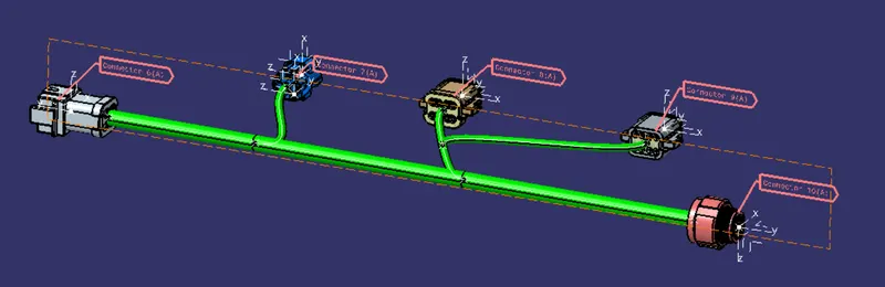
Figure: Harness A
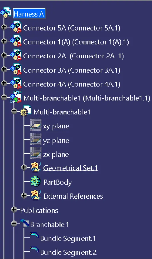
Figure: Expanded Tree (1)
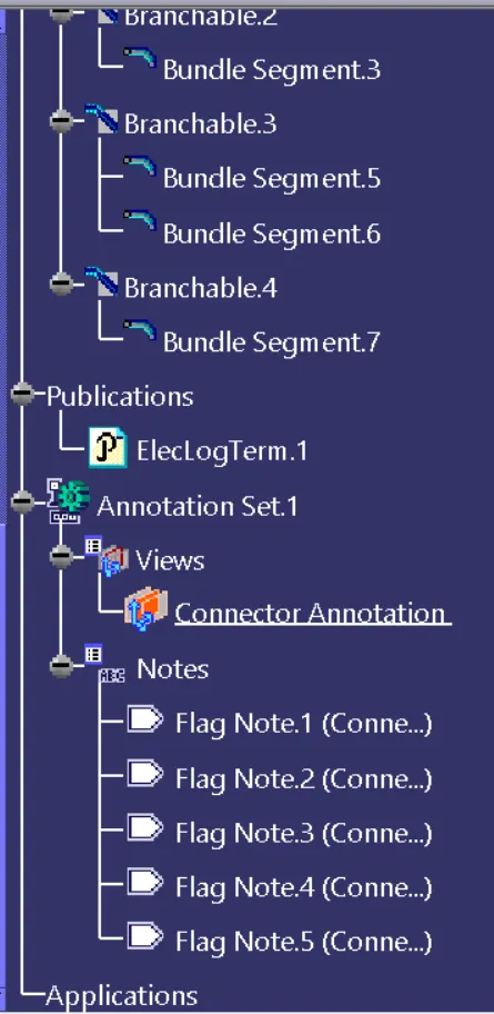
Figure: Expanded Tree (2)
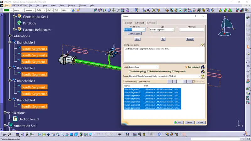
Figure: Connectivity Check of Harness A
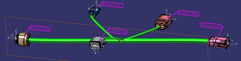
Figure: Harness B
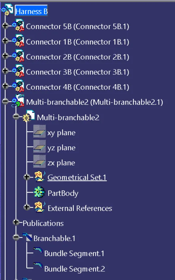
Figure: Expanded Tree (1)
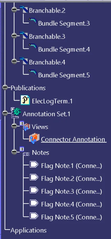
Figure: Expanded Tree (2)
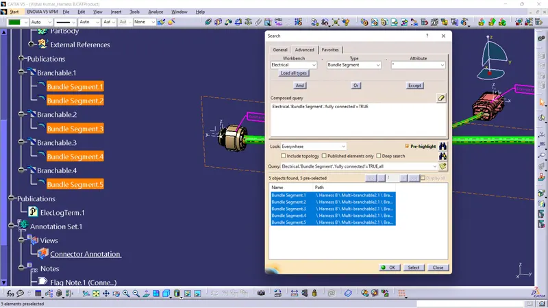
Figure: Connectivity Check of Harness B
Interconnection of Harness A and Harness B
- Further, Create a new Product file named as Harness Assembly to interconnect both the Harness A and Harness B.
- Copy both the Harness files into the new product file and then Switch to Electrical Assembly Design to connect both the harness electrically.
- Use the command Connect Electrical Devices to connect Harness A and Harness B and the male connector gets inserted into the female connector.
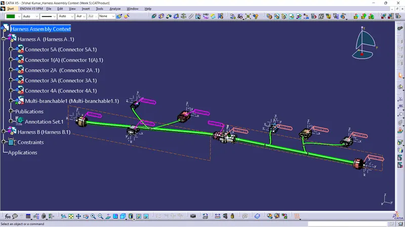
Figure: Interconnection between Harness A and Harness B
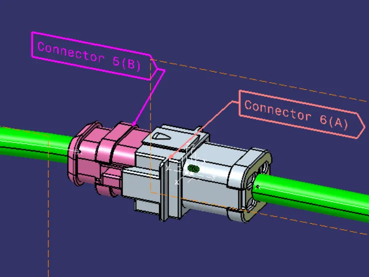
Figure: Interconnection between Connectors
Checking Geometrical Bundle Warning
- Geometrical bundle warnings are shown for bend radius, bundle diameter and vector position.
- So if there is any incorrect value or input regarding these factors then yellow colored flash wiil be appear in the model tree structure next to the branchable with problems.
- These Geometrical warnings can be recified by changing the value of the Slack or reversing the Tanget direction in the Bundle segment
- Required Bundle segment length is always shown in Branch definition dialog box, through that reference we can get an idea of length of bundle segment.
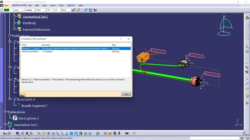
Figure: Bundle Warning in one of the Bundle segment
- This warning is solved by just reversing the tangent of the bundle segment
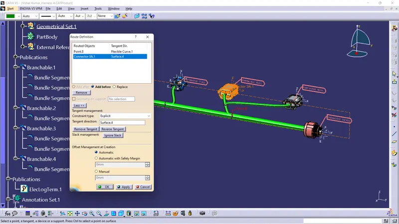
Figure: Bundle warning solved by reversing the tangent direction
Generation of CAT.Part and convert it to igs format
- Next, switch to Mechanical Assembly design Workbench and use the command Generate CATPart from Product to convert Harness assembly file into IGES format.
- Once the CAT part is created, the whole product file is converted into a single part.
- Now, whole file is converted into the IGS format and we can see all the harness assembly is looking in grey color.
- If required we change the colour of each bundle segment as required.
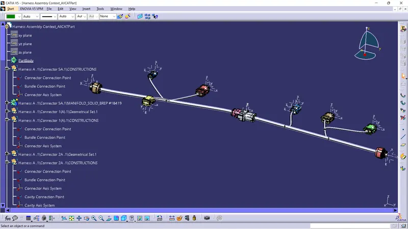
Figure: CATPart file
- To save CAT part file as IGS file, we have to use 'Save as' option in IGS format.
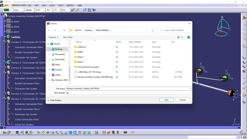
Figure: Saving as IGS format