Week 8 - Challenge 1 - Base Bracket Design
Aim: To Create a Base Bracket Plastic Component using the given Class A surface.
Report on the Draft Analysis and the Creation of the tooling axis
- From the given Class A surface, connectivity of the Class A surface is checked by using the boundary command. The given Class A surface has 3 boundaries ie., one Outer boundary and two inner circles boundaries.
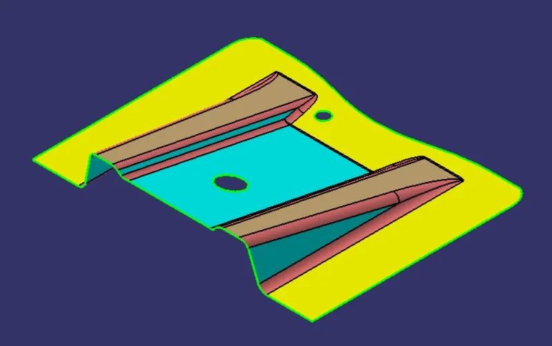
Figure: Class-A Surface
- Tooling Axis is the direction in which the mould or the core and cavity opens.
- Check visually for the best possible tooling axis. From the Y-direction it is not possible, from the X-direction it is possible but it is complicated and not economical friendly and from the Z-direction it is possible. Hence, a “Dummy Tooling Axis” is created in the Z-direction.
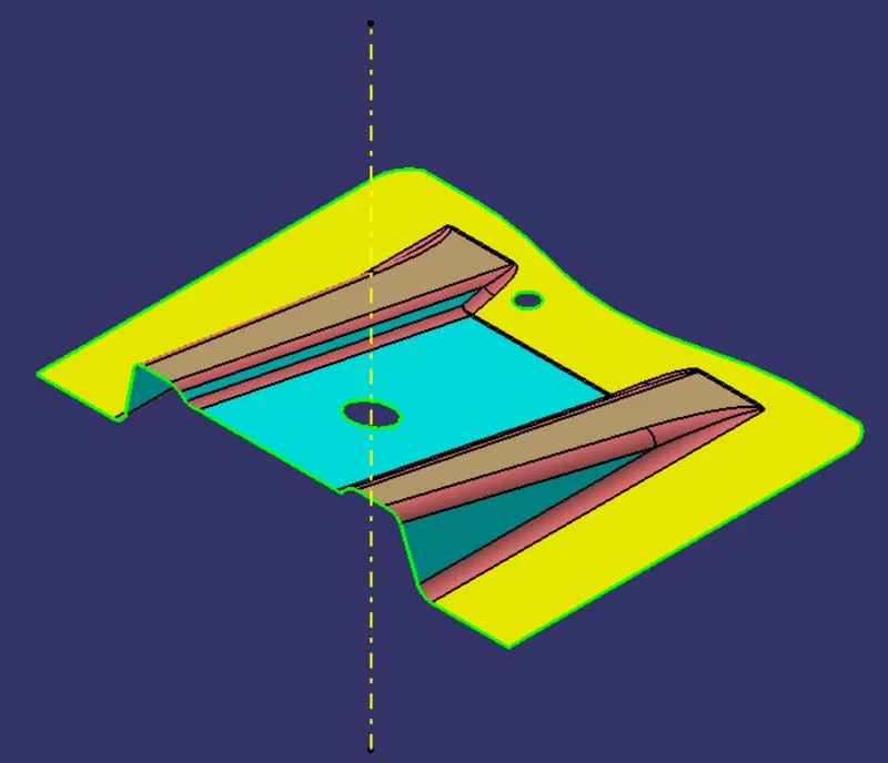
Figure: Dummy Tooling Axis
- Using the ZX plane as the reference, an intersection is made on the Class A surface.
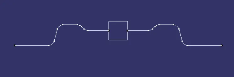
Figure: Intersect made on the Class A Surface
- Using point-point command, two lines are created taking two inclined lines as the reference.
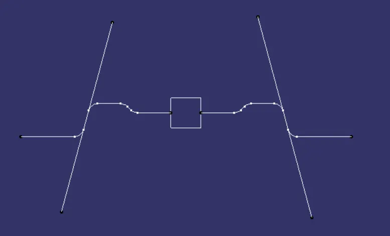
Figure: Reference lines for creating Bisecting line
- Further, New line is created using the bisection method taking the previous created lines as the reference.
- This Bisecting line in the Z-direction is to be referred as the “ Tooling Axis”.
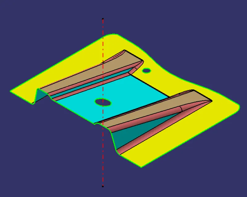
Figure: Tooling Axis on the Class A Surface
- Next, Draft analysis is done on the Class A surface by taking the compass on the Tooling Axis.
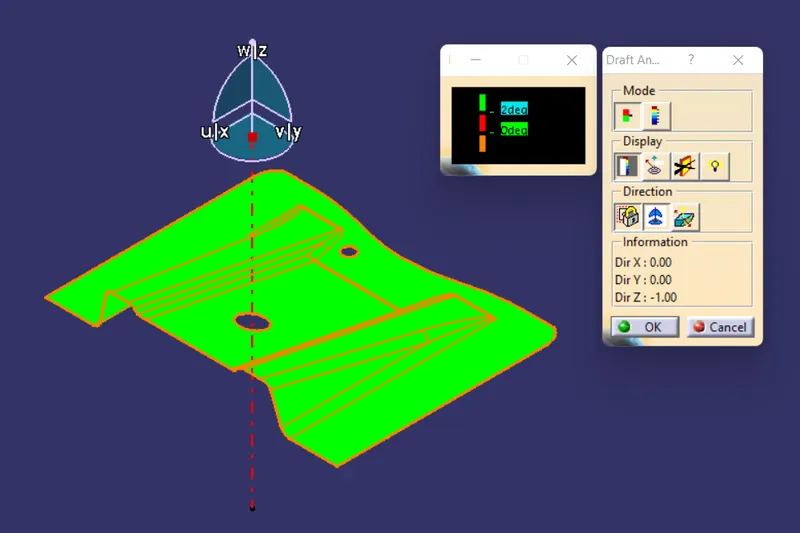
Figure: Draft analysis done on Class A Surface.
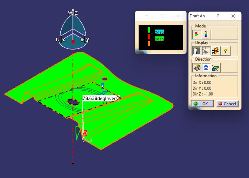
Figure: Draft Analysis on Class A surface
Creation of Class B Surface:
- Firstly, the side ribs are extracted from the Class A surface and then Untrimmed and extrapolated.
- Next, trim the required surfaces and offset it to 2.5mm
- Similarly, the slanted and the flat base are extracted and offset to the required value and then perform the trim operation on it
- Finally apply fillet it.
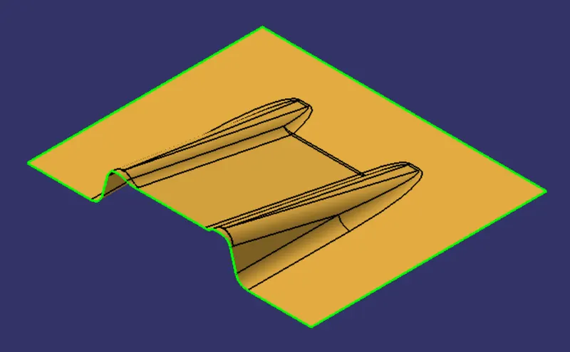
Figure: Class B surface
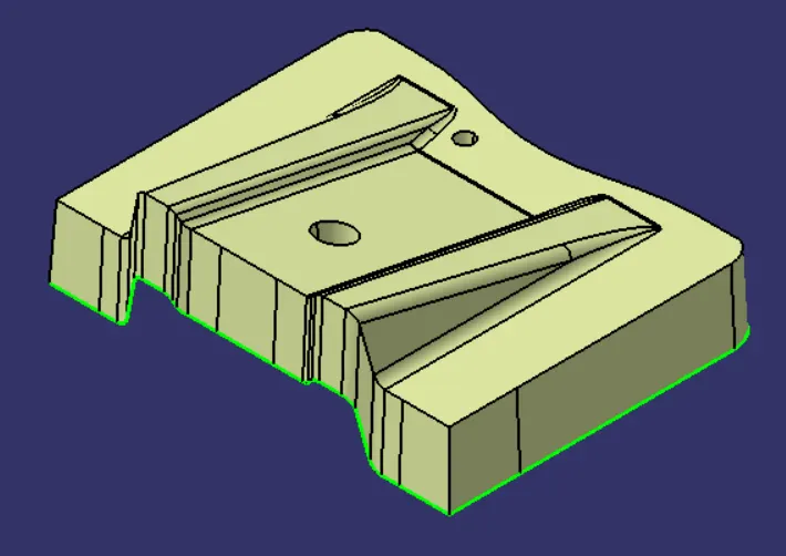
Figure: Class C surface
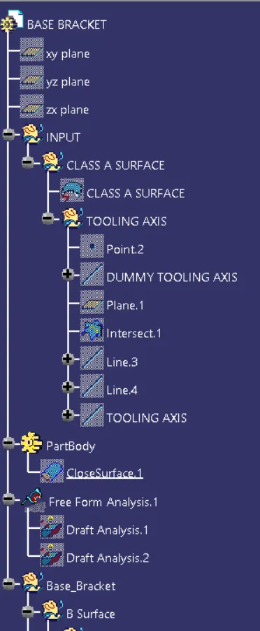
Figure: Expanded Tree (1)
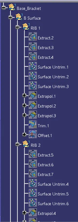
Figure: Expanded Tree (2)
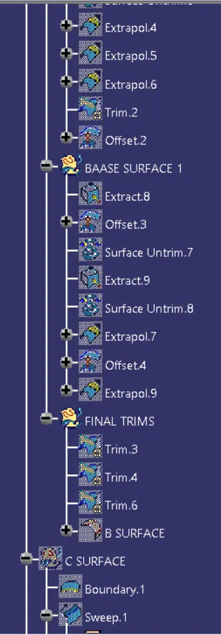
Figure: Expanded Tree (3)
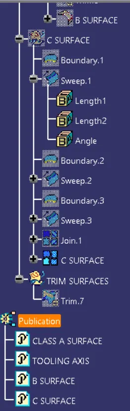
Figure: Expanded Tree (4)
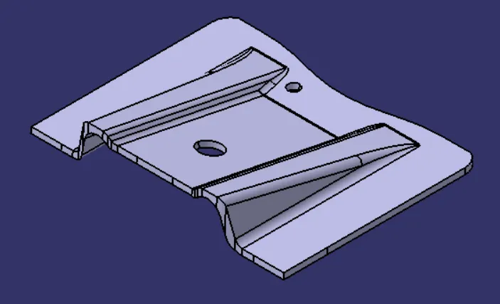
Figure: Isometric View of Closed Surface
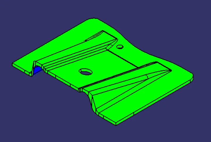
Figure: Isometric View of Draft analysis of Closed Surface
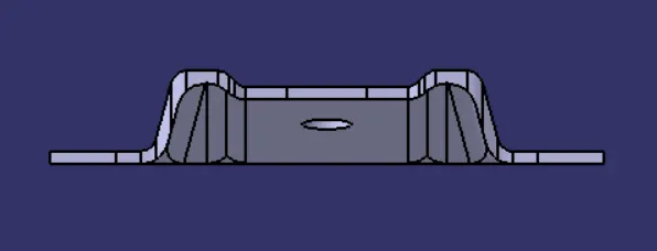
Figure: Front View of Closed Surface
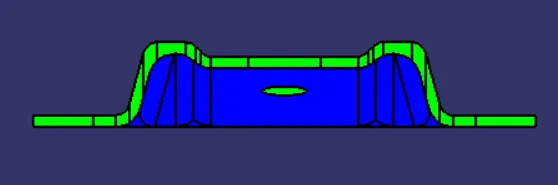
Figure: Front View of Draft Analysis of Closed Surface
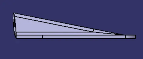
Figure: Side View of Closed Surface
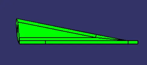
Figure: Side View of Draft analysis of Closed Surface
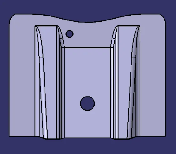
Figure: Top View of Closed Surface
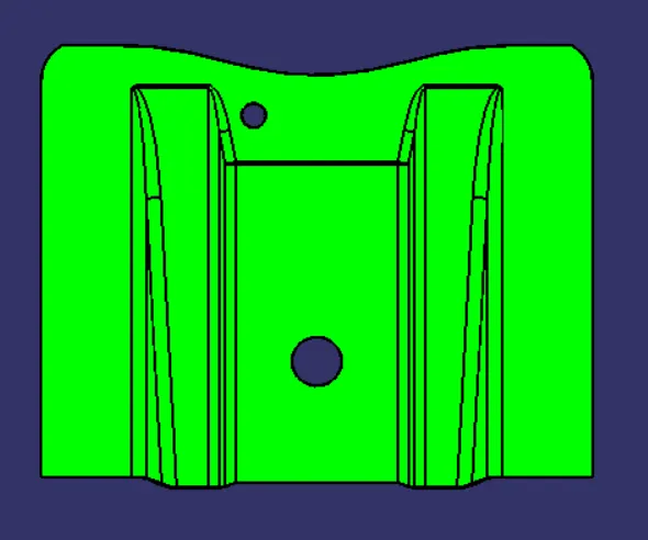
Figure: Top View of Draft Analysis of Closed Surface
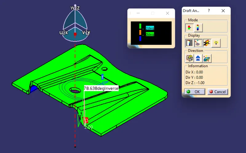
Figure: Isometric View of Closed Surface in Draft Analysis