Photo Realistic Rendering
American Chopper Motorcycle Design Project using Solidworks
Objective:
- The objective of this project to learn the Solidworks interface and simultaneously sketch or model different exterior parts of American Chopper
- To assembly different parts of Chopper under the assembly environment
- To create a Photorealistic model of the chopper and Render the model using Solidworks Photoview 360 and Solidworks Visualise
Introduction about American Chopper:
A American Chopper is a type of custom motorcycle which emerged in California in the late 1950s. The American Chopper is perhaps the most extreme of all custom styles, often using radially modified steering angles and lengthened fork for a stretched out appearance. The rider sits with upper torso upright or leaning slightly rearward. The foot pegs are in such a position such that the rider has to extend his/her legs forward. Some of the Characteristic features of chopper are long front ends with extended forks often coupled with an increased rake angle, hardtail frames (frame without rear suspension), very tall “ape hanger” or very short “drag” handlebars, lengthened or stretched frames, and larger than stock front wheels.
Design Tool: Solidworks
Solidworks is a solid modelling CAD (Computer Aided Design) and CAE(Computer Aided Engineering) published by Dassault systems. Solidworks Software used to create 2D & 3D models. It helps to design products better, faster and more cost-effectively.
Design Methodology:
The exterior parts of the American chopper are firstly been sketched on the Solidworks interface and the parts are then been assembled together on the Solidworks Assembly. Finally, the American Chopper is rendered on the Photoview 360 and Solidworks Visualize. The flowchart of the process is shown in the figure below.
Flowchart:
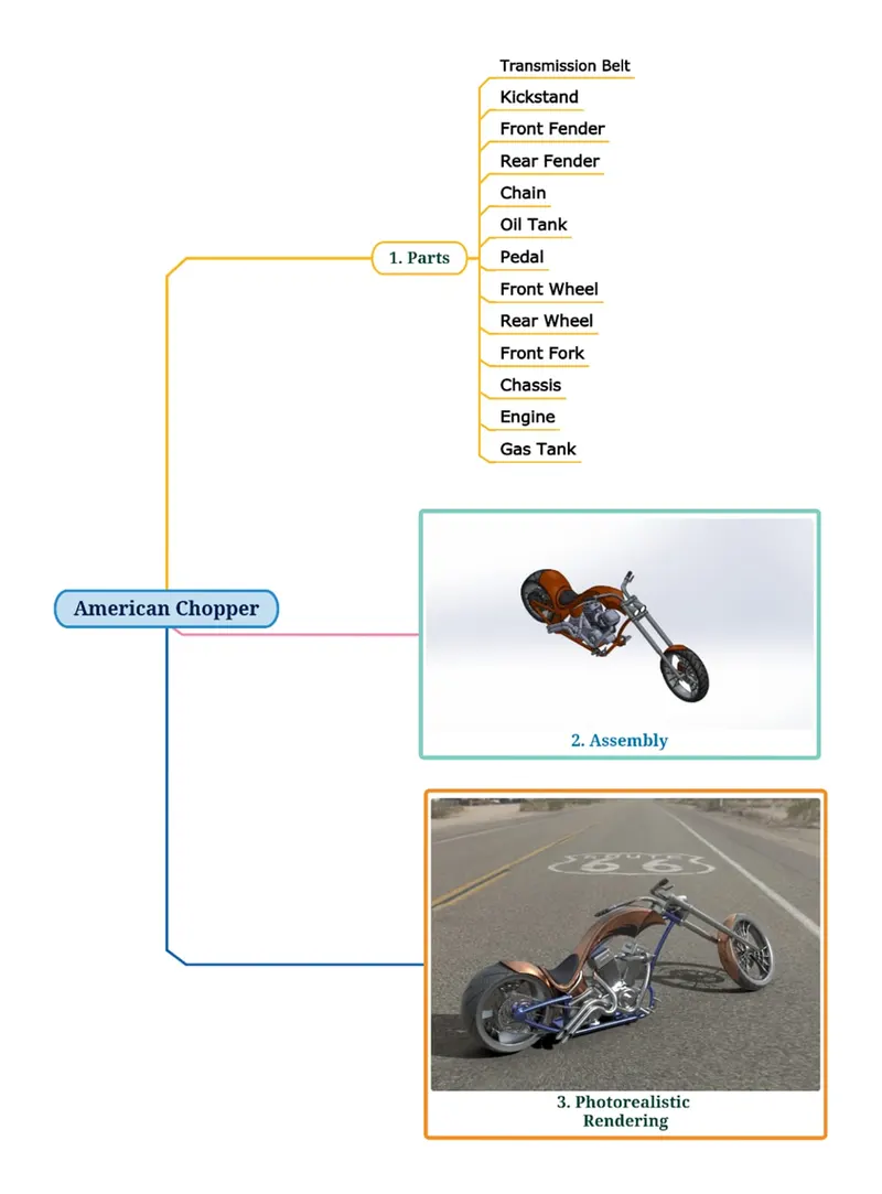
Figure 1: Flowchart of the Procedure
Introduction of Part Modelling:
The American Chopper was modelled using the part modelling. Each exterior part was modelled separately and then assembled them together with proper connections and alignments. The individual parts involved in designing the Chopper Bike are as follows:
- Transmission Belt
- Kickstand
- Front Fender
- Rear Fender
- Chain
- Oil Tank
- Pedal
- Front wheel
- Rear Wheel
- Front Fork
- Chassis
- Engine
- Gas Tank
Part Modelling:
Modelling in general means to create a visual prototype of an item. The 3D part is the basic building block of any large-scale design. Using parameters, we determine the shape and the geometry of the solid metal or the assembly. Parameters include numerical values such as length, radius and geometry as well as horizontal, vertical, tangency etc., Some features such as extrude boss, extrude cut, loft, revolve, fillet, chamfer etc., are used in converting 2D sketches to 3D models and determine the shape of the model as required by the user.
File format in Solidworks: .SLDPRT
Description:
Solid modelling of all the parts of all the American Chopper and its sketches as well are explained are briefly in it as follows:
- Transmission Belt
Transmission Belt is a machine component mostly made out of rubber canvas material and is used to drive the chain shaft driven by the engine flywheel.
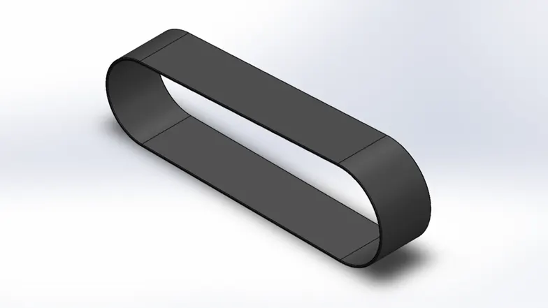
Figure 2: Transmission Belt
Commands Used:
- 3-Point arc
- Line
- Sketch offset
- Fillet
- Boss Extrude
- Appearance
Procedure:
- Select the Front plane and begin the sketching on it.
- Draw a two 3-point arc of radius 70mm and 61mm respectively and along with a horizontal line of length of 350mm defining the distance between the centre of the arcs.
- Draw lines above and below connecting both the arcs.
- Make both the arcs tangent to all the points of the arcs.
- Apply Sketch offset of 3.5mm on the whole sketch in outside direction.
- Extrude the sketch region to 88mm
- Apply fillet of 1mm on the edges of the belt.
- Apply the appearance of matte rubber on it and save the part.
2. Kickstand
Kickstand is also known as Side stand. It is a machine component made of strong material and used to support the chopper in rest position. It is generally attached on the lower side of the chassis and is provided with free movement up to 90 degrees so that it can be moved to and fro when required.
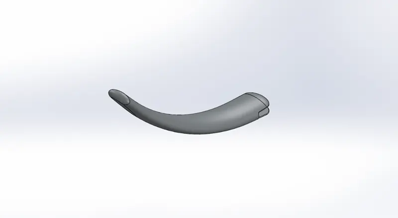
Figure 3: Kick stand
Commands used:
- Ellipse
- Spline
- Pierce
- Boss Extrude
- Cut Extrude
- Fillet
- Split
- Loft
- Dome
- Appearance
Procedure:
- Select the Front Plane and begin sketching on it.
- Sketch an ellipse of width 40mm and height 18mm and make its centre coincident with the origin.
- Sketch a spline on Mid Plane which is perpendicular to the Front Plane and giving it appropriate weight of 225 and proper dimensions from the origin.
- Create a reference plane perpendicular to the spline.
- Sketch a ellipse on the reference plane of height 12mm and width 30mm and make it pierce with the spline drawn.
- Apply loft feature by selecting both the ellipse as the profiles and selecting the spline as the centreline curve.
- Apply Elliptical dome on both faces of ellipse of 13mm and 5mm respectively.
- Sketch a rectangle on the new plane of 8mm width and 28mm length and centre point of the rectangle coincident with the origin.
- Selecting the above sketch apply Extrude cut feature through all on both sides.
- Sketch a horizontal line of dimension 50mm and coincident with the origin at the distance of 4.5mm from it on the reference plane created before.
- Apply Split tool on the above sketch and remove the unwanted part.
- Sketch a circle of 9mm diameter with origin as the centre and apply Extrude boss feature up to the next.
- Apply fillet of 2mm and 0.5mm on the required edges of the kickstand.
- Apply an appearance of chromium on the kickstand and save the part.
3. Front Fender
Fender or mudguard are parts of the automobiles, motorcycles or other vehicle body that frames a wheel well. Its objective is to prevent sand, mud, rocks, liquids, and other road spray from being thrown into the air by the rotating tire.
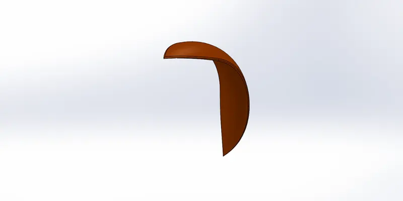
Figure 4: Front Fender
Commands used:
- Line
- 3-point arc
- Sketch Offset
- Spline
- Fillet
- Split
- Revolve
- Dynamic mirror entity
- Appearance
Procedure:
- Rename Front plane, Top plane and Right plane as Vertical Plane Front Fender, Centre plane Front Fender and Midplane Front Fender respectively.
- Select the Vertical Plane Front fender and begin sketching on it.
- Sketch a 3-point arc of radius 125mm and distance between the endpoints of the arc as 160mm.
- Apply horizontal relation between the endpoints of the arc and also apply the vertical relation between the centre of the arc and origin at distance of 280mm.
- Apply Offset feature on the entire sketch of 6mm and sketch two vertical lines from the endpoints of the arc to apply the extend entities feature and trim the unwanted one from the sketch through Trim entities feature.
- Sketch a 200mm horizontal construction line from the origin.
- Apply Revolve boss feature and use the above construction line as axis of rotation with direction 1 =5⁰ and direction 2= 130⁰.
- Select centre plane Front fender and Sketch a construction line of dimension 34mm vertical upward from the origin and Apply dynamic mirror entities feature on it.
- Sketch a Spline from the upper end of the construction line to the other end of the fender and the other spline appears as well due to dynamic mirror feature and Provide appropriate dimensions and weights on it.
- Apply Split Feature on the above sketch and remove the unwanted part.
- Select the vertical plane Front fender and sketch a construction line vertical downward from the origin to the inside edge of the fender and apply dynamic mirror entities on it.
- Sketch a spline with appropriate dimension and the other spline appears as well.
- Use Split feature and remove the unwanted part.
- Provide a fillet of 6mm on the appropriate edges of the fender.
- Apply the appearance of Sieana metallic paint on it and save the part.
4. Rear Fender
A Rear fender is chopper part which is mounted to the rear side of the chassis and is used to cover the upper side of the rear wheel. Its primary objective is same as of the Front fender to protect the wheel from dirt, mud, gravel etc., This part is also known as mud guard.
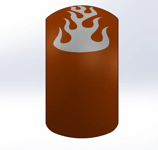
Figure 5: Rear Fender
Commands Used:
- 3-point arc
- Line
- Spline
- Sketch offset
- Revolve
- Split
- Fillet
- Shell
- Appearance
Procedure
- Rename Front plane, Top plane and Right plane as Vertical plane rear fender, Centre plane rear fender and Midplane rear fender respectively.
- Select the Vertical plane and sketch a 3-point arc of radius 290mm and distance between the end points of the arc to be 364mm. Apply horizontal relation between the endpoints of the arc.
- Apply a vertical relation between the centre of the arc and the origin and the distance between the centre and the origin to 90mm.
- Sketch a horizontal construction line from the origin and apply a sketch offset of 6mm inward.
- Sketch horizontal lines on the each end point of the arc and Apply extend entities and Trim entities to remove the unwanted.
- Apply Revolve feature with the construction line as the axis of the rotation with direction1=10⁰ and direction2=140⁰.
- Select the Centre plane and sketch a 3-point arc of radius 265mm and apply horizontal relation between the endpoints of the arc.
- The distance between the centre and origin to be 227mm and vertical relation is also applied between them.
- Use split tool by selecting the above drawn sketch and remove the unwanted part.
- Provide a fillet of 45mm and 4mm on the appropriate edges of the rear fender.
- Apply Shell feature of 4mm on the inside face of the Rear fender.
- Apply appearance of Sieana metallic paint on the part and save the part.
5. Chain
A Chain is a type of transmission system that is used to transmit a power from the Engine to the rear wheel. A chain is a set of several links made up of small plates and pin joints connected in a loop. The Sprocket are used to transmit the power to the chain. Sprocket is connected to the shaft with the of key. It has high power transmission capacity, good flexibility, cost effective and it is of high maintenance.
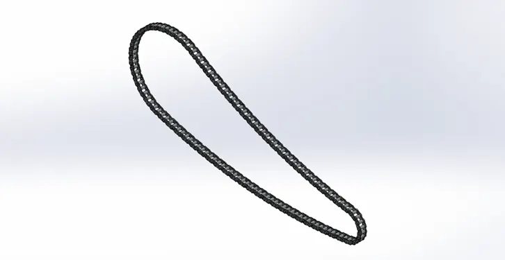
Figure 6: Chain
Commands Used:
- Circle
- Line
- 3-point arc
- Trim entities
- Slot
- Make Block
- Extrude boss
- Fillet
- Curve driven pattern
- Mirror
- Appearance
Procedure:
- Rename Front plane, Top plane and Right plane as Midplane Chain, Centre plane chain and Front plane chain respectively.
- Select the Midplane and Sketch two Circles of diameter 289mm and 99mm respectively and give horizontal dimension of 650mm and vertical dimension of 147mm between the centre of the circles.
- Sketch a 3-point arc of radius 1500mm on the circles both up and down and apply the tangency relation between the circles and the arcs.
- Apply Trim entities feature and remove the unwanted and we get the path of the chain.
- Create two link plates with circular pins of diameter 8mm and distance between the centres as 15.13mm and select both sketched linked plates and make the as Blocks and save them.
- Now insert the blocks on the chain path by applying the relations of coincident and concentric.
- Extrude the circular pins midplane to dimension of 25mm and extrude the link plate1 to 2mm by a offset 9.5mm and also extrude the link plate2 to 2mm on the inside vertex of the link plate1.
- Apply a fillet of 0.5mm on the circular pins of the link plates.
- Apply curve driven pattern by selecting the pins and both the plates at an equal distance of 30.26mm of 20no’s on the longer arc path only.
- Select all the pins in solid bodies folder and save them in new folder.
- Insert the blocks again on the smaller circle and apply the curve driven pattern selecting the appropriate bodies.
- Follow the same instruction on the remaining path as well providing the extrude, fillet and curve driven pattern with required distancing and required no’s.
- Use Mirror feature by selecting only the link plates of the chain.
- Apply the appearance of the chromium plate on the chain and save the part.
6. Oil Tank
Oil tank is a component of chopper used as a reservoir to meet the oil requirements of the engine and to lubricate the parts. It contains flammable liquid safely and its hollow in nature. The oil tank used in this American chopper is placed right below the seat of the rider on the top pf the gearbox.
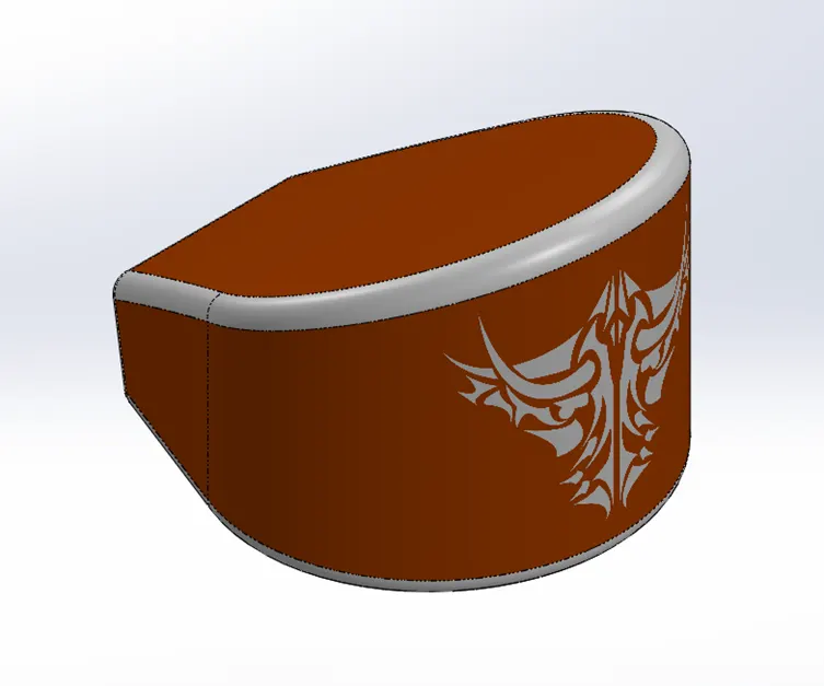
Figure 7: Oil Tank
Commands Used:
- Line
- 3-point arc
- Dynamic mirror entities
- Extrude
- Combine
- Fillet
- Shell
Procedure:
- Rename Front plane as Midplane Oil tank and select Top plane to begin sketching.
- Sketch a horizontal construction line of 230mm from the origin and sketch a point at the vertical distance of 144mm from the origin.
- Apply Dynamic mirror entities feature on the horizontal line and sketch a vertical line of 50mm and further continue with an angled line and complete the sketch with an arc.
- Make the angled line collinear to the point sketched before and apply the tangent relation between the angled line and arc.
- Extrude the sketch 110mm in direction 1 and 10mm in direction 2.
- Select Midplane and sketch a vertical line upwards from the origin of length 166mm and Sketch an angled line at an angle of 92.5⁰ with the vertical line and further continue to make another angled line and complete the sketch with a spline.
- Extrude the above sketch through all.
- Use the combine feature on both the bodies to get the desired.
- Apply a fillet of 10mm on the edges.
- To get the hollow oil tank apply the shell feature of 3mm.
- Apply an appearance of Sieana metallic paint on the Oil tank and White colour on the edges which were filleted.
- Add decal on the face of the Oil tank and Save the part.
7. Pedal
It is an external part attached to the chassis and used to rest the foot of the rider on to it for the purpose of comfort. For the rider on the manual bike, the footpegs also include a rear brake lever on the right-hand side and a gear lever on the left. In a chopper type motorcycle, the pedals are placed in forward position such that the legs of the rider are fully extended in a comfortable manner. The pedals also contain protruded sections so as to provide grip to the rider’s foot to avoid any kind of slippage. They are also called as Footpegs.
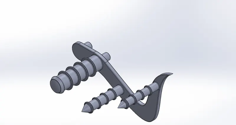
Figure 8: Pedal
Commands Used:
- Line
- 3-point arc
- Spline
- Circle
- Sketch Fillet
- Extrude
- Revolve
- Dome
- Fillet
- Chamfer
- Linear pattern
- Appearance
Procedure:
- Select the Front plane and begin the sketch.
- Create the following sketch as shown in figure.
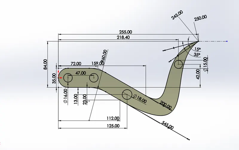
Figure 9: Sketch on the front plane
- Apply sketch fillet of radius of 60mm as shown in above figure.
- Extrude the complete sketch including the circular holes to 8mm Blind.
- Again, extrude the circles of diameter of 16mm in reverse direction 20mm.
- Apply a fillet of 1mm on the outside and inside faces of the Pedal.
- Select the Top plane and sketch as follows.
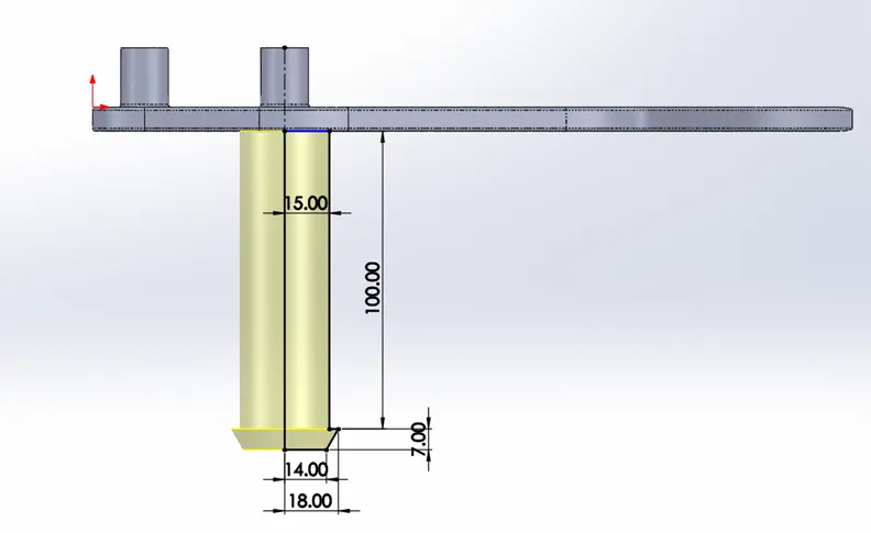
Figure 10: Sketch on the Top plane
- Apply revolve feature on the above sketch with merge result.
- Apply a 3mm Dome on the footpeg and apply a fillet of 1mm on the appropriate edges.
- Now, extrude the smaller circles of diameter 18mm and 15mm to 100mm.
- Apply Distance-Distance Chamfer on the extruded rods of diameter of 18mm and 15mm to a distance of 16mm and 9mm and to a distance of 16mm and 7.5mm respectively.
- Apply offset of 2.5mm and 2mm on the smaller extruded circles and on the revolved rod.
- Now extrude those sketches by 2.5mm and to a offset of 20mm rom the plane.
- Apply fillet of 1mm on the intersection of footpegs and shifters and on the upper face of it.
- Apply linear pattern on them to a equal distance of 20mm to 4 no’s
- Apply an appearance of chromium plate on the Pedal and save the part.
8. Front Wheel
It is a circular object that revolves on an axle and is fixed below a vehicle or other object to enable it to move easily over the ground. It is present at the Front of the vehicle and it contains of the following components such as Rim, Rotor, Calliper, tyre.
Front wheel of the chopper is always larger than the rear wheel. The front wheel of the American Chopper has a diameter of 604mm and the tyres have a narrow surface contact and are generally made up of rubber to ensure flexibility and bump absorption. The tyre contains threads for the grip on the road. The Wheel also has Rotor and Calliper.
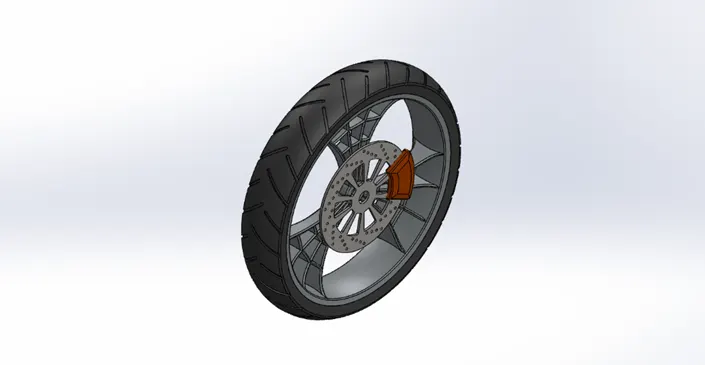
Figure 11: Front Wheel
Commands Used:
- 3-point arc
- Line
- Spline
- Circle
- Midpoint line
- Circle
- Extrude boss
- Fillet
- Extend entities
- Trim entities
- Chamfer
- Combine
- Circular pattern
- Revolve boss
- Sketch Fillet
- 3-point rectangle
- Appearance
Procedure:
- Select the Front plane and begin sketching
- Sketch a horizontal mid-point line of 110mm on the origin and sketch a 40mm vertical line on the both ends of the horizontal line and close the sketch by a horizontal line from both end points of the vertical lines making it a rectangle.
- Next, Sketch a horizontal line of 140mm at a distance of 330 mm from the origin and draw a vertical construction line of 28mm from the midpoint of the line and make it coincident to the origin.
- Draw two equal tapered line at an angle of 75⁰ from the horizontal line towards the origin and apply horizontal relation between the end points of the line.
- Sketch a 3-point arc of radius 230mm from the endpoints of the tapered line and make the midpoint of the arc and end point of the vertical construction line coincident.
- Apply 5mm sketch fillet on the corners and create a revolve about the midpoint line at the origin.
- Select the Right plane and sketch a vertical construction line of 320mm from the origin and draw another line of same dimension at an angle of 31⁰ to the vertical line.
- Next draw a horizontal line of 22.5mm from the origin to the left of it and draw a 3-point arc between the vertical construction lines and make it concentric to the origin.
- Sketch a spline from the endpoint of the horizontal line to the vertical construction line and apply appropriate dimension of 340mm.
- Apply Mirror entities on Spline, 3-point arc, Horizontal line & vertical construction line.
- Now, Extrude the above sketch to the midplane of 122mm and deselect merge result.
- Next, sketch a vertical construction from the origin to the top edge and apply an offset of 9mm inside on the remaining edges.
- Draw two vertical construction lines at a distance of 9mm apart from the bottom edge of the spoke to the offset line and the rightmost line at a distance of 2.5mm from the origin.
- Next, draw a vertical construction line at an angle of 9⁰ to the vertical line from the origin to upper arc and sketch a spline from the vertical 9⁰ reference line to the endpoint of 2.5mm offset line and make the lowerpart handle of the spline vertical of 300mm dimension.
- Also sketch another spline from the endpoint of 9mm offset line to the upper arc and make the lowerpart handle vertical of 300mm dimension.
- Dimension the two endpoints on the upper arc as 9mm and Use mirror entities and mirror two splines about vertical construction line.
- Extrude cut through all both and deselect the auto select option from feature scope and assign only the required body to cut.
- Sketch 3 circles of diameter 215, 350 and 485 respectively from the origin and convert then into construction.
- Offset each one of the spoke inward about 4.5mm. Use power trim to remove excess entities and to get intersection points between the offset and the construction circle.
- Now, sketch a 3-point arc between the intersecting points and top most arc of equal radius of 200mmand the next middle arc will be of equal radius of 75mm. The bottom most arc on the end will have an equal radius of 15mm and centre arc has an radius of 20mm.
- Apply offset of 8mm on each group of arcs and use trim tool to remove the excess unwanted part and also sketch lines between the endpoints that are open
- Apply Extrude boss upto vertex on both direction 1 and 2 by choosing ends on the each side and deselect the auto select option and choose the spoke.
- Start a new sketch on the front plane and apply intersection curve on the internal face of the Rim and make sure to delete the bottom curve formed and convert he upper arc in to construction
- Next, sketch a vertical construction line from the origin and then sketch a horizontal construction line of 20mm to the left of the origin and continue with a horizontal line and then draw a vertical line above the end point of the arc and then create a line back to the arc with a tangent relation.
- Sketch a spline from the endpoint of the tangent reference line to endpoint of the line at the bottom and make the lower handle of the spline vertical with dimension of 525 and apply tangent relation between the line and upper handle with dimension of 150.
- Apply Mirror entities on the spline and 3 straight lines across the vertical construction line.
- Use Revolve cut about one of the horizontal line and remove it only from the spoke and hub.
- Apply circular pattern by selecting the spoke as the bodies about any circular reference edge up to 3no’s and combine all the spokes, hub and rim making the ma single solid body.
- Apply 4mm fillet on the front and back face.
- Select the right plane and sketch a circle of 345mm diameter from the origin.
- Extrude the above sketch to 7mm thickness about an offset of 45mm.
- Now, select the front face of the rotor and sketch a 8mm diameter circle at a distance of 160mm from the origin.
- Apply linear sketch pattern on the circle at equal spacing of 20mm up to 4 instances at angle of 320⁰. To make the sketch fully defined construct a horizontal line and apply an angle of 140⁰.
- Apply extrude cut up to next only on the rotor and also apply circular pattern up to 14 instances by selecting the outer edge of the rotor.
- Construct two circles of diameter 100mm and 240mm from the origin and sketch two exaggerated lines passing through both the circles at angle of 25⁰ between them and make one of the line vertical and both the lines coincident to the origin.
- Use power trim tool to remove unwanted excess entities and apply extrude cut up to next and deselect the auto-select and choose only the rotor.
- Apply 5mm fillet on inside four corners of the extruded part and use circular pattern on the outside edge of rotor on the extruded cut part up to 10 instances.
- Again, sketch on the right plane, a circle of 40mm diameter from the origin and use extrude cut through all both and remove it.
- Sketch circles of diameter of 200mm and 380mm from the origin on the front face of the rotor and draw two lines between the inner and the outer circle at an angle of 54⁰ between them and draw another vertical construction line from the origin at an angle of 63⁰ to the upper edge.
- Use trim tool to remove the unwanted and apply boss extrude of 10.5mm on both direction 1 & 2.
- Apply distance-distance chamfer on both sides of the caliper of 6mm and 20mm as distance 1 & 2 respectively.
- Apply 8mm fillet on the outside upper and lower edges and 4mm fillet on the outside edges on the front and back of the part.
- Select the front plane and apply the intersection curve and remove the bottom instance.
- Construct two equal tapered lines having a distance of 154 on the upper edge and draw a 3-point arc of radius of 113mm between the end points of the lines and apply the coincident relation between the origin and the centre of the arc.
- The distance between the centre of arc and origin be 280.7mm and apply sketch fillet of 7mm on both the corners.
- Apply revolve on the above sketch using one of the temporary axis as the reference axis.
- Now, select the front plane and choose the edge of the rim to apply convert entities and convert them into construction line.
- Sketch two centre point rectangle of equal width of 8mm and lengths of 138mm and 90mm respectively. The distance of left lowermost point of the larger rectangle and left uppermost point of the smaller rectangle be 20mm and 25mm respectively from the reference line.
- The angle between the lower edge of the larger rectangle and the reference line be 130⁰ and the distance between the left lowermost point of larger rectangle and the left uppermost point of the smaller rectangle be 50mm and 29mm respectively from the origin.
- Again, sketch two centre point rectangle on the right side of the tire of same dimension as the previous one’s. The distance between the left lowermost point of the larger rectangle and the left uppermost point of the smaller rectangle be 63mm and 46mm respectively from the origin.
- The distance between the left uppermost point of smaller rectangle and the reference line be 96mm and the angle between the lower edge of the larger rectangle and reference line be 50⁰.
- Apply extrude cut offset from surface of 4.5mm from the tire surface at an offset of 450mm
- Apply full round fillet on the side faces and centre faces of the extruded cut.
- Apply circular pattern on the threads of the tire up to 14 instances by selecting any one of circular edges as reference.
- Apply an appearance of matte rubber on the tire, painted metallic on the caliper and chromium on the rotor and the rim. Finally save the part.
9. Rear Wheel
Rear wheel of the chopper is generally smaller in diameter than the front wheel. The rim of the wheel is an important strength component which provides safe load carrying capacity and high compressive strength. The tyre of the wheel has broad section for better surface contact, heavy load carrying capacity and greater grip. The rear wheel also has a disc brake rotor and its calliper and specifically a chain sprocket to drive the wheel using power transmitted from the engine.
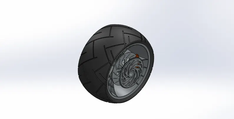
Figure 12: Rear Wheel
Commands Used:
- Line
- 3-point arc
- Revolve boss
- Spline
- Mirror entities
- Extrude cut
- Convert entities
- Trim entities
- Offset entities
- Circular pattern
- Fillet
- Intersection curve
- Revolve cut
- Centre point rectangle
- Appearance
Procedure:
- Select the front plane and sketch a midpoint line and then finish it off as rectangle with length of 300mm and width of 45mm.
- Construct a horizontal line of 320mm and 273mm from the origin and then draw two equal lines tapered at angle of 75⁰ towards the origin from the endpoints of the horizontal line. Complete it by sketching a 3-point arc of radius of 600mm in between the endpoints of the tapered line.
- Sketch a vertical construction of 40mm from the midpoint of the horizontal line to the midpoint of the arc and make the line coincident to the origin. Apply 5mm sketch fillet on the corners.
- Apply revolve for the above sketch about the line form the origin.
- Select the right plane and sketch a vertical construction line from the origin and another vertical construction line of same length as previous one at an angle of 31⁰. Then sketch a horizontal line of 22.5mm to the left of the origin.
- Next sketch a 3-point arc of radius 265mm and make the centre of the arc coincident to the origin.
- Sketch a spline from the endpoint of the 22.5mm line to the endpoint of the arc and make the lower handle of the spline vertical with 300mm.
- Use mirror entities on the arc, spline and the horizontal line across the vertical reference line.
- Apply midplane extrude of 300mm on the above sketch.
- Again, select the right plane and apply an offset of 9mm inward on the left spline, horizontal line and right spline.
- Use convert entities on the upper arc and remove the extended entities by power trim tool.
- Construct vertical construction line from the origin to the upper arc and sketch another vertical line at an angle of 9⁰ to the above.
- Construct two vertical construction lines between the offset and lower part at 9mm apart and the leftmost line at 2.5mm from the origin.
- Sketch a spline from the endpoint of 9⁰ vertical line to the endpoint of 2.5mm line and make the lower handle vertical with dimension of 300mm.
- Construct another spline from the endpoint of the 9mm line to the upper arc and make its lower handle vertical with dimension of 300mm.
- Use mirror entities on both the spline across the vertical construction line.
- Apply extrude cut of through all both on the spoke.
- Start another sketch on the right plane and sketch three construction circles of diameter194mm, 298mm and 403mm respectively. Apply an offset of 4.5mm on each side of the spoke and convert them into construction.
- Use power trim tool to remove the unwanted excess sketch and to get the reference point we need.
- Now sketch 3-point arc between these points. The uppermost arcs be equal of radius of 75mm and the 2nd arcs be equal of radius of 25mm. Finally, the centre arc of the bottommost be of 20mm radius and the other arcs outside be of 15mm radius.
- Apply an offset of 8mm on the arcs and use power trim tool to remove the excess. Sketch lines between the open endpoints of the spider web.
- Apply an extrude of up to vertex on both the directions 1 & 2 by selecting the vertices on the spoke.
- Apply circular pattern on the spoke up to 3 instances and use combine feature to add spokes, hub and the rim.
- Select the Front plane and sketch a vertical construction line and a horizontal line of 25mm from the origin. Apply intersection curve feature on the inside face of the rim and remove only the bottom curve formed.
- Convert the upper curve into construction and sketch a line tangent to curve and coincident with the edge of the rim.
- Then draw a vertical line and next draw a horizontal line to meet the previous horizontal construction line.
- Sketch a spline from the endpoint of tangent line to left endpoint of the horizontal construction line and make the lower handle vertical with 300mm and upper handle tangent with 200mm
- Use mirror entities on the spline, horizontal line, vertical line and the angled line across the vertical construction line.
- Use Revolve cut about one of the horizontal lines and remove it from the part.
- Apply a 3mm fillet on the left- and right-hand side of the outside face of the spoke.
- Sketch a circle of diameter 60mm from the origin on the right plane and use extrude cut through all both directions to get a hole.
- Sketch the following as shown in figure
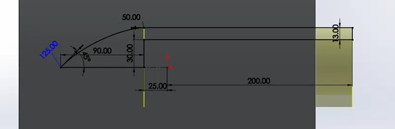
Figure 13: Sketch on the Front plane
- Create a solid revolve on the above sketch and merge result with the Rim.
- Select the right plane and select the outside diameter of the revolve and apply convert entities feature. Next, draw a circle of diameter 320mm from the origin.
- Apply boss extrude of thickness of 7mm at an offset of 105mm.
- Select the outside face of the rotor and sketch a 8mm diameter circle at a vertical distance of 145mm from the origin.
- Use linear pattern of equal spacing of 15mm up to 4 instances at an angle of 230⁰ on the left-side. Sketch a horizontal construction line and the angle between it and 1st reference line be 130⁰.
- Use extrude cut up to next and select only the rotor as feature scope.
- Use circular pattern up to 14 instances by selecting the circular edge of the rotor.
- Again, select the outside face of the rotor and sketch circles of diameter 90mm and 210mm respectively. Sketch a vertical line between two circles and an angled line also at an angle of 25⁰ to the vertical line and use power trim tool to remove the additional unwanted information.
- Apply extrude cut up to next on the rotor and also apply fillet of 5mm on the inside edges of the extrude cut.
- With extruded cut selected apply circular pattern on the rotor up to 9 instances.
- Select the outside face of the rotor and sketch circles of diameter 180mm and 360mm respectively. Construct two exaggerated lines passing through both the circles at an angle of 54⁰ to each other and 63⁰ to the front plane and coincident to the origin.
- Use power trim tool to remove the unwanted and apply extrude midplane to the thickness of 30mm with a reverse offset of 3.5mm.
- Apply distance-distance chamfer of 6mm and 20mm as distance 1 & 2 on both the faces of the calliper and to be applied separately on the faces.
- Apply a fillet of 8mm and 4mm on the two corners of the calliper and the outside edges of the calliper respectively.
- Select the axle and convert outside edge to an entity and sketch a circle of diameter 300mm.
- Extrude it in reverse direction to the thickness of 15mm and also apply a chamfer of 4mm and 45⁰ on the outside edges of the sprocket.
- Sketch the following as shown below on the outside face of the sprocket
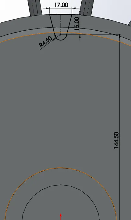
Figure 14: Sketch of the Extrude cut on the sprocket
- Apply Extrude cut feature through all by selecting the sprocket and apply a fillet of 2.2mm on the two upper edges of the extrude cut.
- Provide circular pattern up to 16 instances around the circular edges.
- Select the outside face of the sprocket and sketch two circles of diameter 90mm and 255mm respectively. Sketch a offset circle of 203mm diameter at a horizontal distance of 50mm and vertical distance of 35mm from the origin.
- Use tool such as offset, power trim, extend entities to get the following sketch
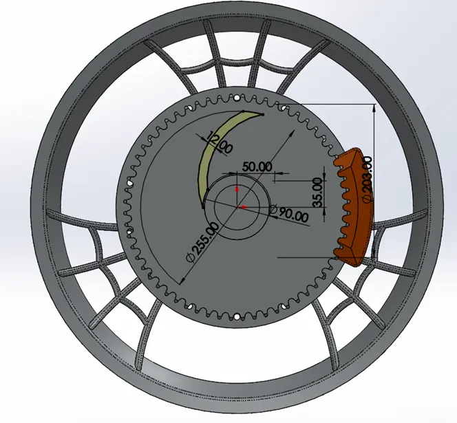
Figure 15: Sketch of the extrude cut
- Apply extrude cut through all on the above sketch by selecting the sprocket.
- Again, select the front face of the sprocket and sketch two circles of diameter of 255mm and 172mm respectively and sketch an offset circle of 135mm diameter at a distance of 50mm horizontal and 35mm vertical from the origin.
- Use tools such as offset, power trim, extend entities to get below sketch.
- Apply extrude cut through all by selecting the sprocket.
- Apply a fillet of 1mm on all the edges of the extrude cut by selecting the faces of the extrude cut.
- Apply circular pattern of extrude cuts on the rotor by selecting the circular reference up to 7 instances.
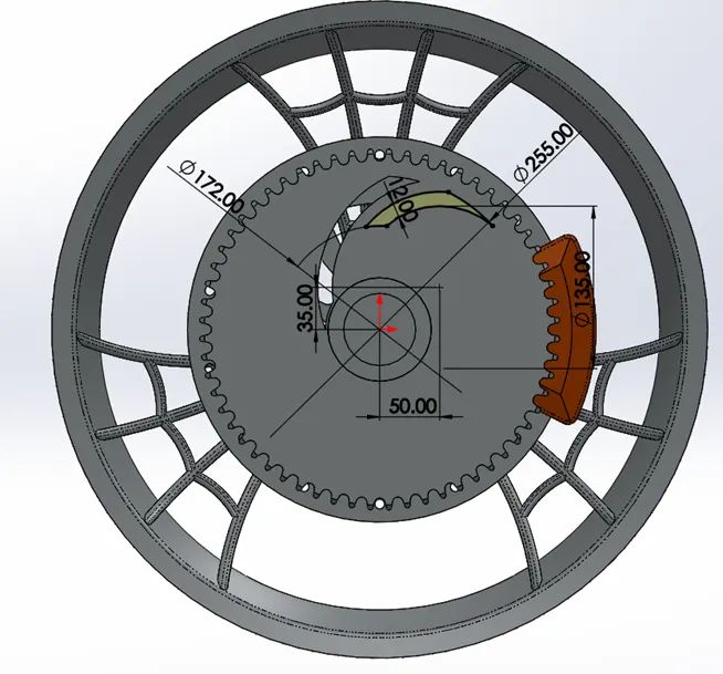
Figure 16: Sketch for the extrude cut
- Select the front plane and apply intersection curve feature on the outer face of the rim and remove the bottom formed edge. Sketch two equal angled lines and a 3-point between the endpoints of the lines with dimension as shown in figure.
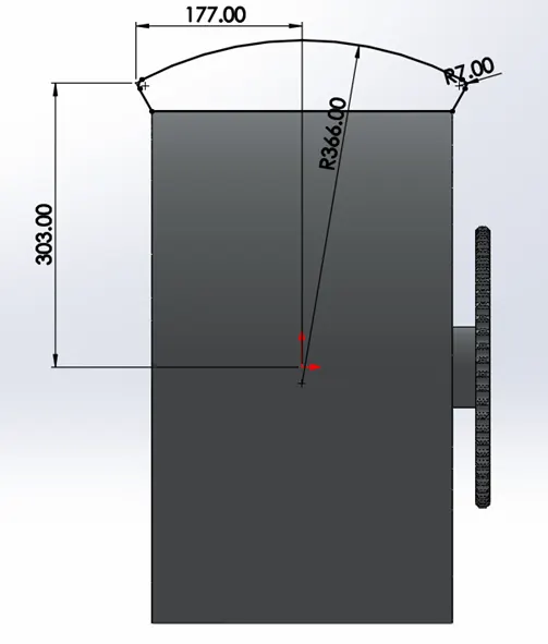
Figure 17: Sketch on the Front plane
- Apply sketch fillet of 7mm on the corners.
- Apply Revolve feature by selecting one of the temporary axes.
- Select the Front plane and sketch two angled centre point rectangle of equal width of 8mm and length of 97mm and 280mm respectively both below the origin. Sketch a horizontal construction line.
- The distance between the right uppermost point of the smaller rectangle and the origin is 10mm below at angle of 40⁰ with respect to horizontal line.
- The horizontal distance between the right uppermost point of the larger rectangle and the origin be 30mm both endpoint and origin being horizontal.
- Sketch another two centre point rectangle of same dimensions as the before one’s as following
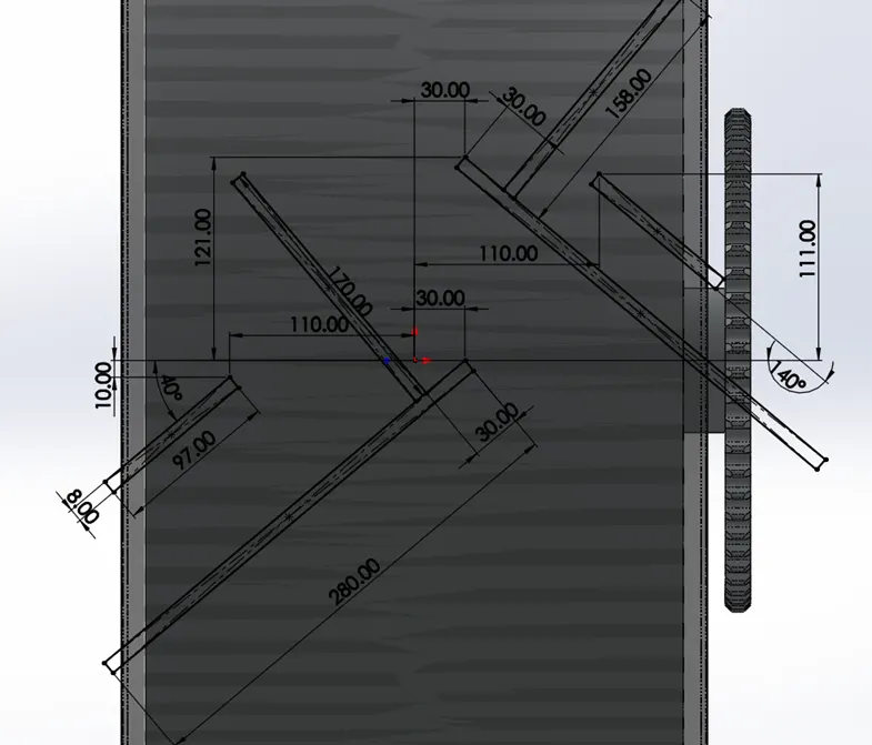
Figure 18: Sketch of the tyre threads
- Apply an extrude cut offset from the surface 6mm away at an offset of 400mm on the tire.
- Apply 4mm fillet on the extruded cuts of the tire and also apply circular pattern up to 9 instances on any of the circular reference.
- Apply an appearance of matte rubber on the tire, chromium plate on the rotor, Rim and Sprocket and painted metallic Siena on the Calliper. Finally save the part.
10. Front Fork
A motorcycle fork connects a motorcycle's front wheel and axle to its frame, typically via a yoke, also known as a triple clamp, which consists of an upper yoke joined to a lower yoke via a steering stem, a shaft that runs through the steering head, creating the steering axis. Most forks incorporate the front suspension and front brake, and allow the front wheel to rotate about the steering axis so that the bike may be steered. Most handlebars attach to the top clamp in various ways, while clip-on handlebars clamp to the fork tubes, either just above or just below the upper triple clamp.
Its efficient design helps in better ride and handling of the motorcycle. It also houses other sub components such as headlights, handle bars, handle grip, Triple clamps, Brake lever, clutch lever, cables and axle.
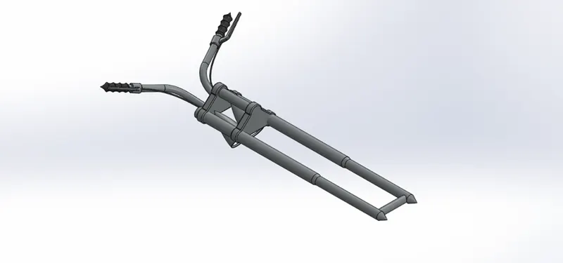
Figure 19: Front Fork
Commands Used:
- Line
- Spline
- Revolve boss
- Revolve Cut
- Convert Entities
- Circle
- Power trim
- Extrude
- Fillet
- Linear Pattern
- 3-point arc
- Move/Copy body
- Dome
- Sweep
- Mirror bodies
- Project curve
- Reference geometry
- Appearance
Procedure:
- Begin sketching on the front plane, sketch the fork tube with proper dimensions as shown in figure.
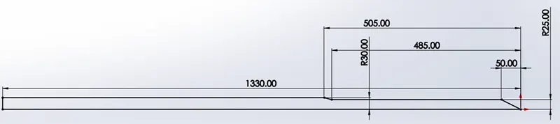
Figure 20: Sketch of the fork tube
- Revolve it about the horizontal line at the origin and select the upper end of the fork tube to start the sketch.
- Using Convert entities convert the outside diameter of the tube and sketch a circle of 75 diameter at the origin.
- Sketch another circle of 80mm diameter from the left of the origin at a vertical and horizontal distance of 100mm and 105mm respectively.
- Sketch a line vertically below from upper quadrant point of 80mm diameter circle and continue the line connecting it to the other circle at 24mm below the origin. Sketch another line from the upper quadrant point of 75mm diameter circle to the right quadrant point of the 80mm diameter circle.
- Use power trim tool to remove the unwanted and get proper fully defined closed sketch.
- Extrude the sketch on to the part to the thickness of 40mm with an offset of 20mm on the part.
- Apply 5mm fillet on the three edges and outside edges of the triple clamp.
- Apply linear pattern on it by selecting triple clamp as the bodies and up to equal spacing of 240mm with 2 instances with one of the temporary axes as the reference.
- Next, sketch a 40mm diameter circle at the horizontal distance of 70mm away from the left of origin on the front plane.
- Extrude the above sketch up to the surface till the face of the triple clamp and merge it only with the fork.
- Select the upper face of the lower triple clamp and sketch a circle of 50mm diameter concentric with the rounded portion of the triple clamp and sketch a vertical line between the upper quadrant point and the bottom quadrant point.
- Extrude the sketch up to upper clamp surface to create an axle between the clamps.
- Sketch the following with proper dimension for headlight bucket.
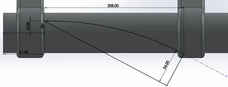
Figure 21: Sketch of Headlight bucket
- Apply revolve operation about the long horizontal line.
- Apply Move/Copy body feature and move the headlight by -48mm in Z-direction.
- Select the outer face of the headlight and apply an offset of 4mm inward. Apply Extrude cut on it up to 10mm with 5⁰ draft inward on the Headlight bucket.
- Apply 3mm and 1mm fillet on the outside and inside edges of the Headlight and provide a dome of 7mm on it as symbolic of lens.
- Select the Dome face and inside face of the Headlight and apply intersection curve feature on it and convert them into construction.
- Next, sketch a construction line form the midpoint and sketch the remaining as shown in figure.
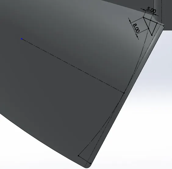
Figure 22: Sketch of the Revolve cut
- Apply revolve cut on the above sketch selecting the horizontal construction line as the axis on the headlight bucket.
- Now, sketch a circle of 35mm diameter at a distance of 50mm from the mirror plane and 24mm from the front plane on the upper triple clamp.
- Select the Top plane and sketch as shown in figure
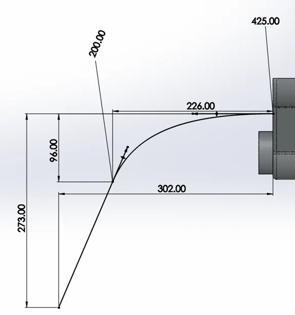
Figure 23: Sketch of the handlebar
- Select the Front plane and apply convert entities feature on the horizontal line of the above sketch and then convert it into construction.
- Now sketch as shown in figure
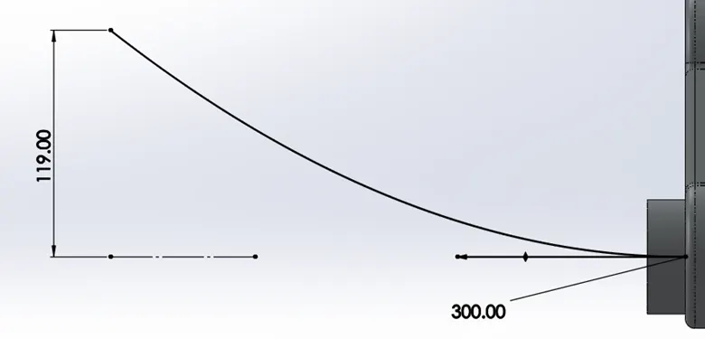
Figure 24: Sketch of Handlebar
- Apply project curves on both of the above sketches and get the curve. Apply Sweep on the curve and taking the circle of above sketch and merge it with only triple clamp.
- Select the end circular end face of the handle bar and sketch a horizontal line in it and making it coincident with the centre point of the circle.
- Create a reference plane about the circular face and the line and sketch about this reference plane.
- Sketch using the commands such line, 3-pooint arc to get the following
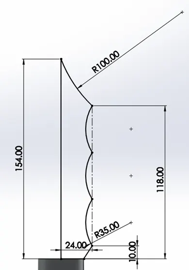
Figure 25: Sketch of the handle grip
- Apply revolve about the horizontal line on the above sketch and merge it with triple clamp and handlebar
- Sketch again on the reference plane and sketch a vertical construction line of 15mm downward and then continue it sketching a rectangle of length 55mm and breadth 25mm vertically below the line.
- Apply revolve on the above sketch and merge it with triple clamp and handlebar.
- Create a new reference plane about the reference plane and one of the temporary axes passing through the centre of the handlebar and at an angle of 160⁰.
- Sketch as shown in figure on the newly created reference plane
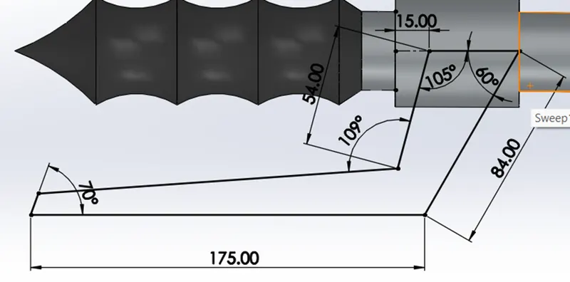
Figure 26: Sketch on the reference plane 2
- Extrude the sketch midplane about 15mm and apply a fillet of 25mm, 5mm and 4mm on the required edges of the extrude.
- Sketch a construction line of 25mm and a circle of 9mm diameter at one of its endpoint on the flat face of the lever.
- Next, sketch the following sketch on the Top plane
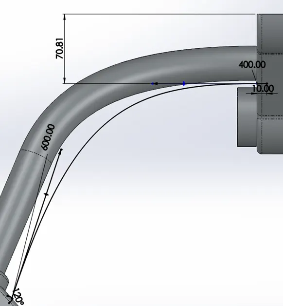
Figure 27: Sketch for the cable
- Apply Project curve feature on the two sketches and provide sweep on it taking curve as the path and merge it with only triple clamp and handlebar.
- Apply Mirror feature on the triple clamp, handlebar and fork with axle about the triple clamp front face.
- Apply combine feature on the handlebar, triple clamp and Front fork.
- Create a new reference plane named as Vertical Front fork about Top plane and temporary axis passing through the axle of the fork at angle of 59⁰ and name this view orientation as Front of Bike.
- Apply an appearance of chromium plate on the entire part. Then, apply an appearance of matte rubber on the brake line(cable) and the grip.
- Apply an appearance of area light on the lens of the headlight bucket with luminous intensity of 1mm/s2 Finally, save the part.
11. Chassis
A Chassis is a pressed-steel frame—the vehicle’s chassis—formed a skeleton on which the engine, wheels, axle assemblies, transmission, steering mechanism, brakes, and suspension members were mounted. These components are directly or indirectly mounted on the chassis. It is made up of high strength material component of any vehicle as it is the base structure and it can withstand variable compressive, tensile and shear stresses.
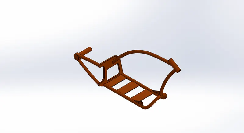
Figure 28: Chassis
Commands:
- Sketch Picture
- Transparency
- Circle
- Line
- Spline
- Sweep
- Mirror
- Convert entities
- Power trim
- Extrude Boss
- Offset entities
- Extend entities
- Trim entities
- Extrude cut
- Chamfer
- Fillet
- Reference geometry
- Dome
- Pierce
- Revolve
- Split
- Combine
- Offset
- Appearance
Procedure:
- Rename the Top plane and Front plane as Bottom plane Chassis and Midplane Chassis.
- Sketch on Midplane Chassis and we bring in the sketch picture of the chopper with x=-930mm and y=-805mm and apply transparency as required.
- Start a sketch on Midplane Chassis and sketch a concentric circle with outer diameter of 40mm with an offset of 4mm and at vertical and horizontal distance of 185mm and 880mm from the origin.
- Select the Midplane chassis and sketch a horizontal line of 710mm from the origin and continue with a spline from the endpoint of the line to the centre point of the circle. Apply tangency on the lower handle of the spline with 200mm
- Select the bottom plane chassis and by using the commands line, spline sketch as follows
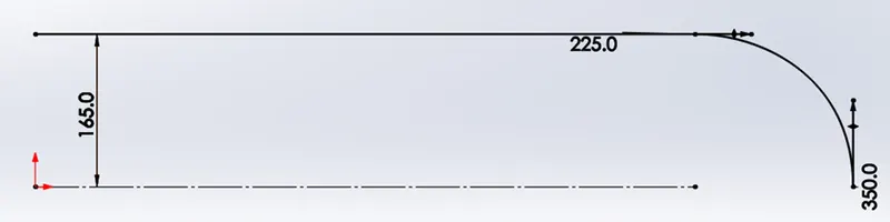
Figure 29: Sketch on Bottom plane Chassis
- Use Project curve feature on both the above sketches.
- Select the right plane and sketch as shown below
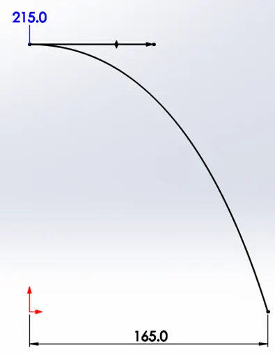
Figure 30: Sketch on the right plane
- Apply Project curve feature on the above sketch and apply sweep by using circle as the profile and curve as the path for the lower section of the frame.
- Apply Mirror feature on it and start sketching on the right plane and view from the back.
- Sketch a circle of 75mm diameter with vertical construction line of 245mm from the centre of the circle such that it is below the origin and been tangent with bottom edge of the tube.
- Apply convert entities on both outside profiles of the tubes and sketch a horizontal line passing through bottom of both the circles and right end point being at a distance of 265mm from the origin.
- Next, continue sketching the lines horizontally and vertically as shown in figure and use power trim tool to remove the unwanted sketches.
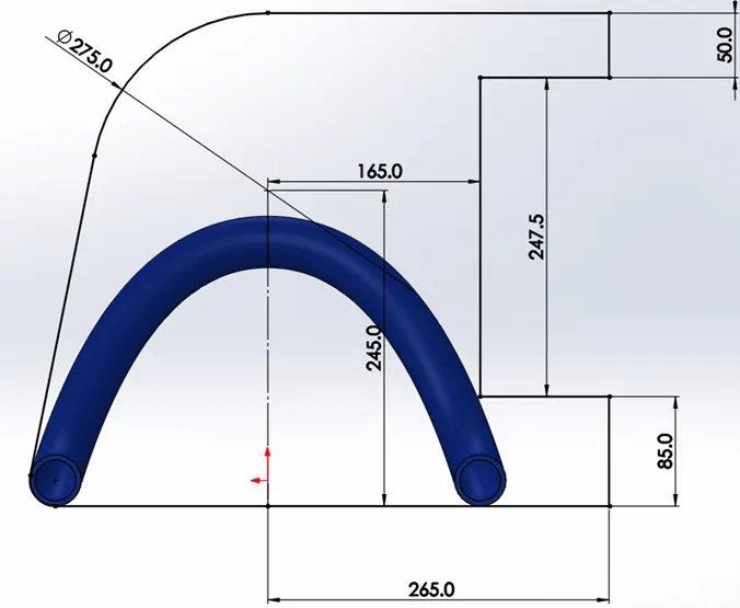
Figure 31: Sketch on right plane
- Apply an extrude of 22mm thickness away from the tubing on the above sketch.
- Start sketching at the back face of the extruded part and apply an offset of 50mm on both the left vertical edge and right angled line edge. Next, sketch two horizontal lines at top and bottom passing through both the horizontal lines and at a distance of 220mm and 30mm respectively from the origin. Use extend and trim entities to get a closed fully defined sketch.
- Apply extrude cut up to next on the above sketch and apply a distance-distance chamfer of 90mm as distance 1 and 44mm as distance 2 on the outer right lower edge of the extrude.
- Apply 25mm fillet on the outside right edges and inside edges and 50mm fillet on the outside edges.
- Create the reference plane from the Midplane and the outside vertex of the extrude.
- Sketch concentric circles with outer circle having an offset of 4mm from the right hand-side fillet and offset between the circles be 5mm on the outside face of the extrude.
- Sketch spline from the centre of the circle at horizontal and vertical distance of 411mm and 305mm from the origin and lower handle of the spline of 350mm and apply sweep feature on the sketch.
- Again, select the outer face of the extrude and sketch concentric circle with outer diameter of 40mm and offset between the circles be 4mm on the outer lower right edge. Then, start sketching on the reference plane a spline with horizontal and vertical distance of 431mm and 260mm from the origin and lower handle of spline be 49⁰ with vertical and 465mm.
- Apply sweep feature on the above sketch.
- Sketch a circle of 95mm diameter with horizontal and vertical distance of 426mm and 280mm from the origin on the reference plane and extrude the above sketch mid-pane of 44mm.
- Sketch a circle of 60mm concentric to the hub created above on the outer face of the Hub and extrude it up to 223mm.
- Apply a Dome of 10mm on the outer face of the axle.
- Begin a new sketch on the Midplane Chassis and sketch a horizontal construction line of 215mm from the left of the origin and sketch splines from the endpoint with the dimensions as shown in figure
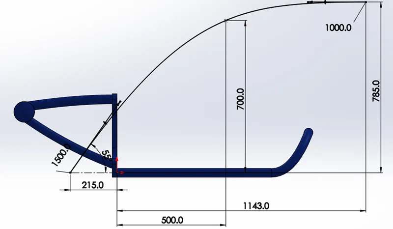
Figure 32: Sketch on the Midplane chassis
- Create a new reference plane about the upper spline of the above sketch and its upper end point. Sketch a concentric circle on the new reference plane with outside and inside diameter of 40mm and 32mm respectively and apply pierce relation between the centre of circles and its spline.
- Apply sweep feature taking spline as the path on the above sketch and use split command to remove the tube section passing through the motor plate.
- Sketch the following figure on the Midplane Chassis
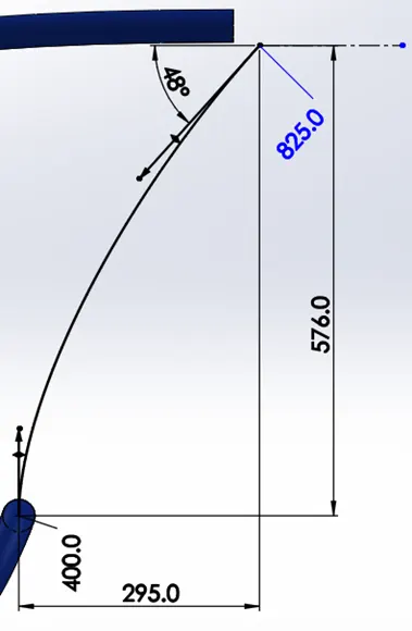
Figure 33: Sketch on Midplane Chassis
- Create the New reference plane with respect to the spline on the above sketch and the lower end point of the spline and start a new sketch on it.
- Sketch concentric circles with outside diameter of 40mm and offset of 4mm between the circles and apply pierce relation between the circle and the spline. Use Sweep feature on the sketch with spline as the profile path.
- Use Split tool to remove the geometry inside the tube.
- Select the Midplane chassis and begin sketching an angled line of 200mm and at an angle of 59⁰ with respect to the vertical construction line and at horizontal and vertical distance of 1041mm and 840mm from the origin near the end of the both tubes and convert it into construction.
- Next, sketch a rectangle of length 200mm and breadth 7.5mm with an offset of 32.5mm with the centre line and parallel to the construction line.
- Apply the revolve feature about the construction line and use split tool to remove the geometry inside the tube. Finally, combine all the tubes.
- Select the Midplane Chassis and sketch a series of horizontal lines from the origin of the dimensions 102mm,102mm,135mm,120mm,135mm and 116mm respectively.
- The 2nd 102mm line, 120mm and 116mm lines are converted into construction and apply an offset of 6mm upwards on the remaining lines and then close those profiles with lines as rectangle.
- Apply boss extrude up to next on both the directions 1&2 on the above sketch.
- Apply 2mm fillet on the outside face of the centre tube and sketch the triangle as shown in figure on Midplane Chassis.
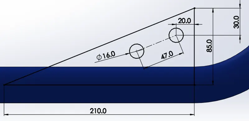
Figure 34: Sketch on the Midplane Chassis
- Extrude the above sketch with an offset of 165mm in midplane with thickness of 10mm and use split toll to remove the unwanted geometry.
- Apply fillet of 20mm on the upper edge of the triangle and 1mm on the outside edges and circular holes edges and mirror the part about the midplane chassis and then combine all of them.
- Begin sketching on the front face of the left frame and apply intersection curve on the tube and remove the unwanted by using the trim tool.
- Then sketch a vertical construction line from the centre of the trimmed circle and an angled line of 50mm at an angle of 120⁰ with the vertical line.
- Apply an offset of 4mm in bi-directional and close the ends with lines and use power trim tool to remove the upper edges. Finally, extrude it 40mm backwards.
- Apply an 20mm fully round fillet on it and then apply an fillet of 3mm on the edges of the kickstand plate, frame plate, axle and hub.
- Sketch a circle of 12mm diameter on the kickstand plate and at a vertical distance of 10mm from the centre of the circle to the upper quadrant point and use extrude cut on it.
- Create a reference plate at a distance of 308mm from the bottom plan chassis and rename it as bottom plane fuel tank.
- Finally, apply an appearance of Sieana painted on it and save the part file.
12. Engine
An engine is a machine designed to convert the chemical energy of fuel into thermal or heat energy and then the thermal energy into mechanical energy or mechanical work. Engine is the main powerhouse of the automobile. Motorcycle engines are generally Internal Combustion spark ignition type. The engine consists of piston cylinder arrangement which powers the motorcycle. Motorcycle engines are generally classified by one of three characteristics the number of cylinders of they possess, the capacity of their combustion chambers or the number of strokes in their power cycle.
This American Chopper motorcycle has a V-Twin type engine consisting of external air-filter, spark plugs one for each cylinder, transmission pulleys, air cooling fins, starter motor, front sprocket chain drive, exhaust pipes and casing for sump and generator.
It also consists of 4 mounting points of the chassis.
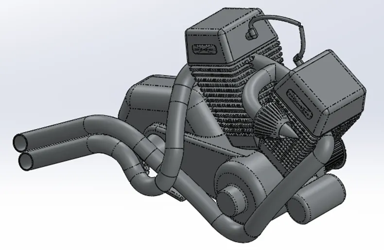
Figure 35: Engine
Commands Used:
- Sketch Picture
- Transparency
- Circle
- Extrude boss
- Extrude Cut
- Line
- Splines
- Fillet
- Revolve
- Curves Projected
- Sweep
- Split
- Reference Geometry
- Offset
- Centre point rectangle
- 3-point rectangle
- Trim
- Circular pattern
- Linear pattern
- Mirror
- Dome
- Combine
- Chamfer
- Appearance
Procedure:
- Sketch on the Front plane chassis and insert the chopper sketch picture using the sketch tool with x=-1493mm and y=-965mm with full image transparency of 0.5 and rename the sketch as the Blueprint Engine.
- Select the Front plane and sketch a concentric circles of diameter 200mm and 80mm respectively with origin as the centre and along with that sketch circle of 130mm diameter at the left of the origin at a distance of 350mm from the origin. Sketch lines having tangency with both the circles
- Extrude the Sketch midplane about 200mm and again select the above sketch and extrude just the circles with centre as the origin about 50mm.
- Next, again extrude the 80mm diameter circle about 40mm from the surface of the extrude.
- Begin new sketch on the front plane and sketch with the dimensions as shown in the figure.
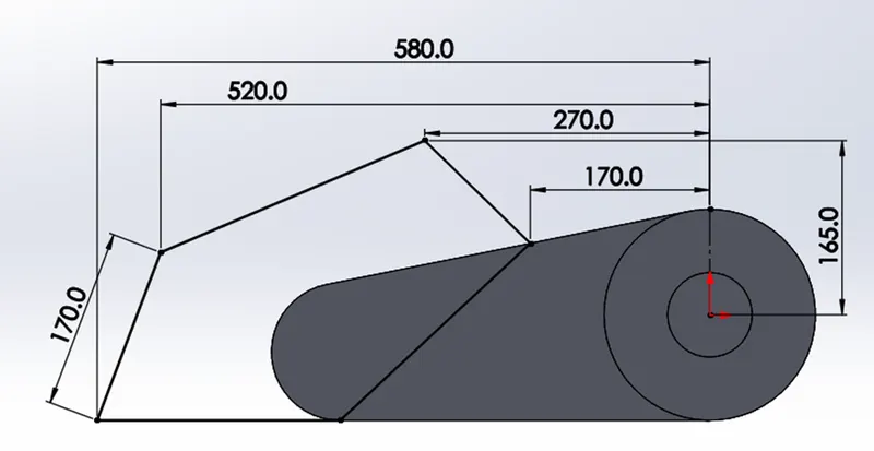
Figure 36: Sketch on the front plane
- Extrude the above sketch in the Midplane about 150mm and apply an fillet of 50mm on the all edges of the extrude.
- Select the right plane and sketch the transmission belt pulley with proper dimensions as shown in the figure
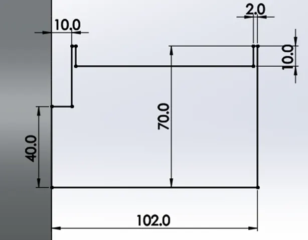
Figure 37: Sketch of transmission pulley on right plane
- Apply an revolve on the above sketch about the horizontal line nearer to the origin.
- Create a new reference plane about the right plane and the below vertex of the 130mm diameter circle. Turn on the temporary axis and begin sketching on the new reference plane the back pulley with same dimensions as shown in the figure.
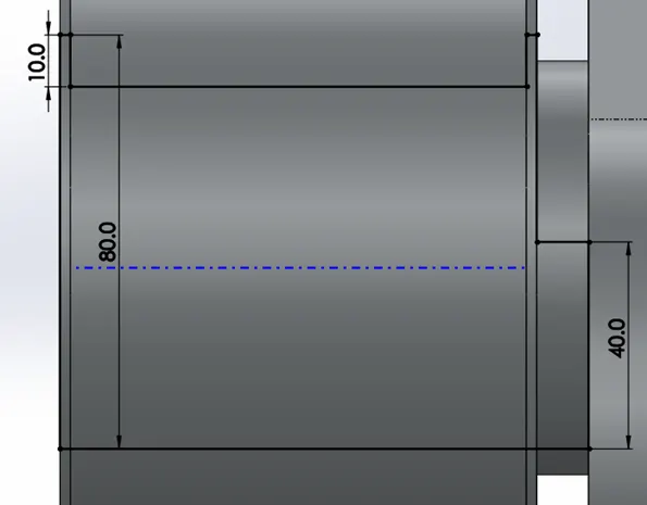
Figure 38: Sketch of Back pulley
- Begin sketching on the back face of the front pulley and bring in the outside and inside edges and convert them into entities. Sketch a centre point rectangle of 5mm wide and 4mm length at the upper quadrant of the lower circle.
- Then the extrude the rectangle up to the inside surface of the pulley and apply circular pattern on it up to 40 instances.
- Use the same procedure on the back pulley with 44 instances of the circular pattern on it and apply Dome feature on the outside of the pulleys of 10mm.
- Next, begin sketching on the Front plane and apply an offset of 30mm inward on the pulley at the origin and sketch a circle of 10mm diameter at a distance of 55mm from the origin and apply circular pattern on it about the origin up to 12 instances.
- Apply extrude cut at an offset of 250mm from dome face of the pulley at offset of 3mm from the surface.
- Follow the same procedure on the back pulley and apply angle distance chamfer of 3mm and 45⁰ at the offset dome face pf the pulleys.
- Apply 1mm fillet on the all outside edges of the pulleys.
- Again begin sketching on the front plane and sketch a circle of 90mm diameter and also construct a horizontal construction line of 155mm from origin to centre of circle and sketch the following with dimensions as shown in figure
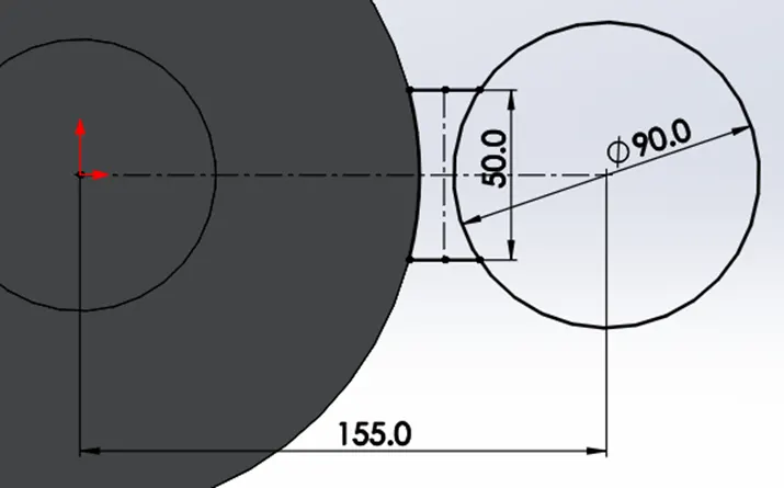
Figure 39: Sketch on the Front plane
- Extrude the circle contour about 150mm at midplane and again extrude the sketch and only the smaller part about 110mm at midplane.
- Begin new sketching on the Front plane and sketch a line of 102mm at origin and another line of 240mm both collinear at an angle of 64⁰ with horizontal.
- Create new reference plane about the 240mm line and its upper end point.
- Sketch on the new reference plane and sketch a centre point rectangle of 190mm both length and breadth at the origin and extrude it till the lower vertex of the line and apply draft angle of 7.5⁰.
- Then, sketch on the end face of the extrude and sketch a centre point rectangle at the origin of 100mm length and breadth and extrude this sketch up to next surface. Finally, again extrude the sketch on the reference plane at the opposite direction of 125mm.
- Apply distance-distance chamfer of 90mm and 15mm on the all four edges of the extrude and apply fillet of 15mm on the appropriate edges of the extrude.
- Select the 2nd created reference plane and sketch two centre point rectangle at the origin of 120mm and 220mm length and breadth respectively and apply sketch fillet of 10mm on the corners of 120mm sketch.
- Extrude the sketch of 8mm at an offset of 26mm and apply linear pattern on the extrude at equal spacing of 16mm up to 14 instances about the vertical 240mm line.
- Apply 2mm fillet on all the edges of the fins created and 10mm fillet on the outside edges of the engine case and of the starter.
- Apply 5mm and 8mm fillet on the all edges connecting the starter motor to the engine and edges connecting cylinder to the engine respectively.
- Start sketching on the outside edge of upper valve cover and sketch a vertical construction line between the midpoints and then sketch 3-point centre rectangle of 100x25mm at the midpoint of the construction line and finally apply 10mm sketch fillet on all corners of the rectangle.
- Extrude the sketch to 2mm and apply a continuous dome of 2.5mm on it and mirror it across the Front plane.
- Sketch the following as shown in figure on the front plane
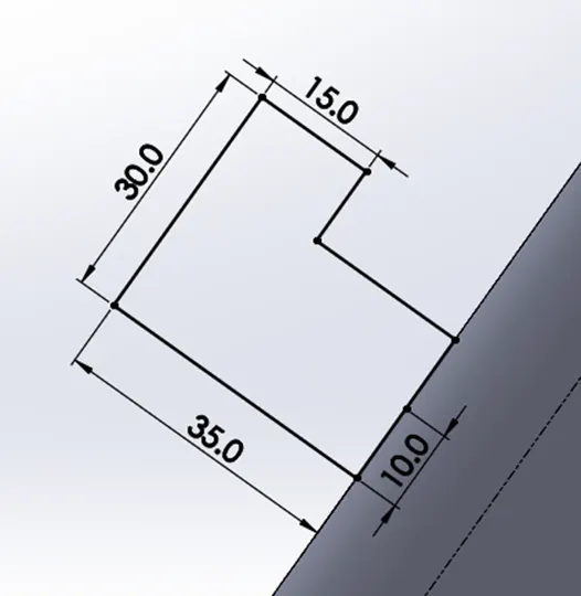
Figure 40: Sketch on the Front Plane
- Extrude the above sketch midplane at 20mm and apply 10mm fillet on the appropriate edges and 2.5mm fillet on the upper face of the extrude.
- Apply split feature to sperate the cylinder from the engine and mirror the cylinder about the right plane on the engine.
- Apply 25mm fillet on the outside edge of the engine case and 4mm fillet to the boss extends on the outside of the case.
- Select the bottom face of the engine and sketch horizontal and vertical construction lines between the edges and then sketch the 3-point centre rectangle as shown in figure.
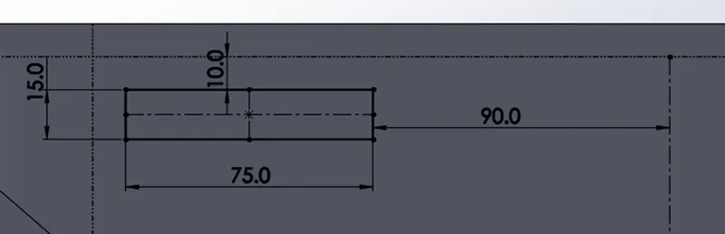
Figure 41: Sketch of the support
- Mirror the entities of the sketch about the vertical and horizontal lines to get support stand on all the corners. Finally, extrude the sketch to 50mm.
- Select the bottom face of the extrude and bring back the vertical and horizontal construction lines and sketch as shown in the figure with the dimensions.
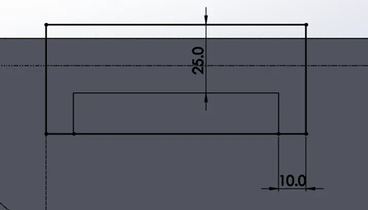
Figure 42: Sketch on the bottom face of the extrude
- Mirror the entities about the horizontal and vertical lines. Extrude sketch to the thickness of 12mm.
- Apply 5mm fillet on the all edges except the bottom edges of the support stand.
- Sketch a 40mm diameter concentric circle on the left side of the front face engine and extrude it to 85mm.
- At the end face of the extruded cylinder, sketch concentric circles of 20mm and 110mm diameter. Extrude the sketch about the 15mm.
- Apply angle distance chamfer of 4mm and 45⁰ on the outside edges of the new extruded part.
- Now, on the front face of the sprocket sketch a 99mm diameter circle and convert into the construction. Then, sketch a circle of 9mm diameter on the lower quadrant of the construction circle.
- Sketch as the following to get the tooth on the sprocket.
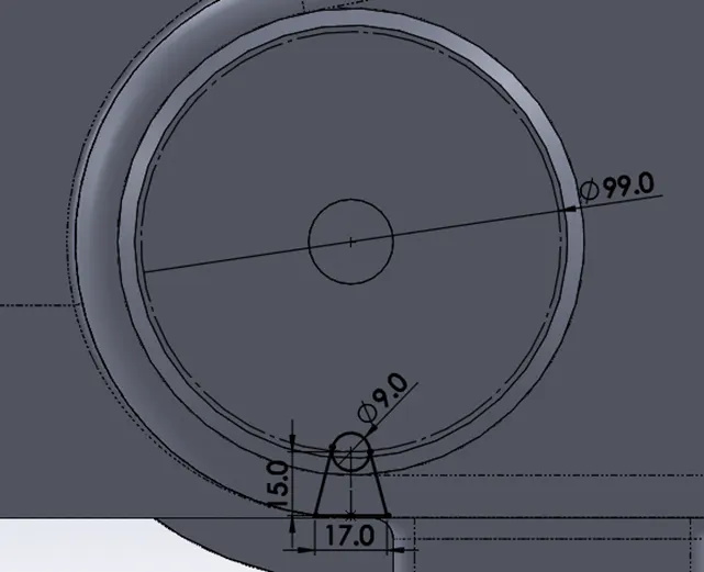
Figure 43: Sketch on the sprocket
- Apply extrude cut on the above sketch up to next and apply fillet of 2.2mm on the outside edges of the tooth. Finally, provide circular pattern up to 21 instances.
- Apply distance-distance chamfer of 24mm and 75mm on the base edge of extruded cylinder of 85mm thickness and also apply angle distance chamfer of 5mm & 45⁰ on the smaller open end of the sprocket.
- Select the Front plane and sketch a vertical construction line of 300mm and other construction line at an angle of 20⁰ to the vertical. Also, sketch a 373mm radius 3-point arc such that its midpoint is coincident with the vertical line upper end point.
- Next Sketch concentric circles with an offset of 4mm and outer circle diameter be 45mm on the endpoint of the vertical line at the right plane. Apply sweep on the circular sketch with arc as the profile path and then mirror the sweep body across the right plane. Finally, Combine all the bodies.
- Create a new reference plane with top plane and circle of 4.5mm diameter as sketch on the arc as shown in figure
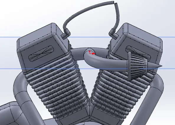
Figure 44: New created reference plane
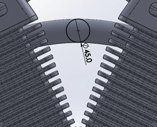
Figure 45: Sketch of the circle
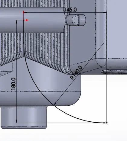
Figure 46: Sketch of the arc
- Apply sweep feature with circle as the profile and the arc as the path.
- Create a new sketch on the reference plane as shown in figure
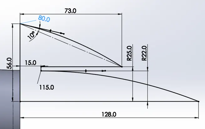
Figure 47: New sketch on the reference plane
- Apply on the above sketch about the horizontal centre line and also apply fillet of 5mm on the back and outside edge of the revolve.
- Begin sketching on the top plane and sketch the three horizontal construction lines between the midpoint of the edges of the revolve. The outer construction lines are of equal length of 4mm and sketch a midpoint line of 4mm as base of the triangle at the endpoint of the right-side construction line as shown in figure.
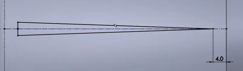
Figure 48: Triangular sketch on the revolve
- Apply an extrude cut on the surface of the revolve of 2mm and also provide circular geometric pattern of the extrude up to 30 instances.
- Sketch the following figures on the front plane and top plane respectively as the exhaust valve.
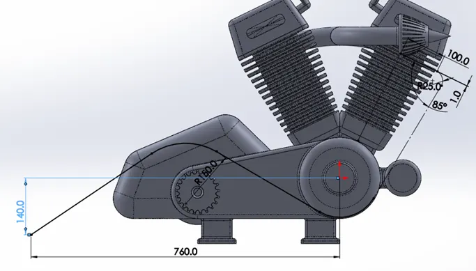
Figure 49: Sketch on the Front plane
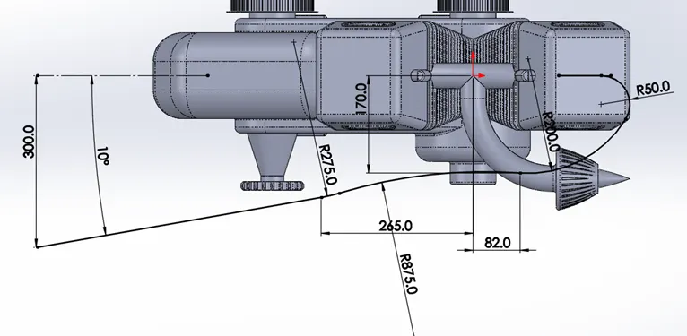
Figure 50: Sketch on the Top plane
- Using the above sketches project the curve and create a new curve using the sketches on the Front plane and right plane as shown in figure respectively.
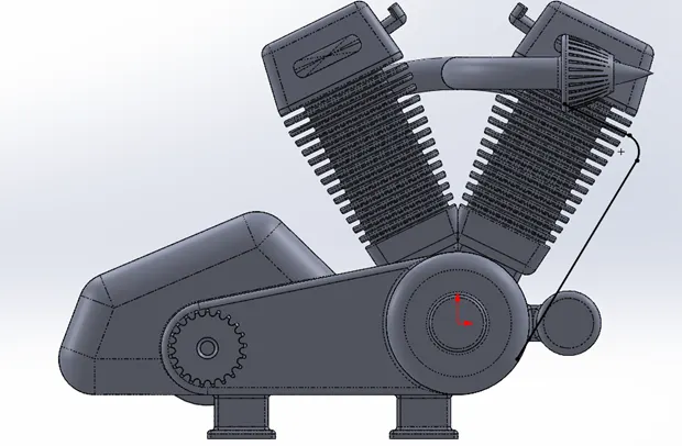
Figure 51: Sketch on the Front plane
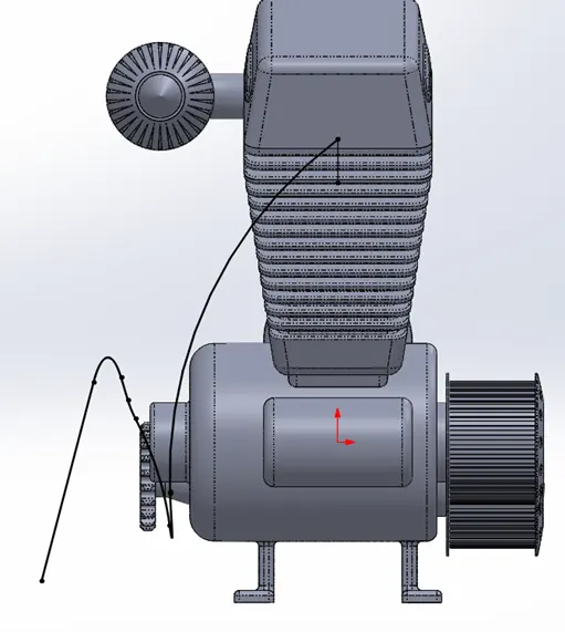
Figure 52: Sketch on the right plane
- Create a new reference plane using the upper edge of the 2nd curve and its upper-end point. Finally, create a composite curve from both the curves 1&2.
- Sketch a concentric circle on the newly created reference plane with outer diameter of 50mm with an offset of 3mm and sweep the sketch along the composite curve.
- Now, sketch the following figures on the front plane and top plane as shown in figure
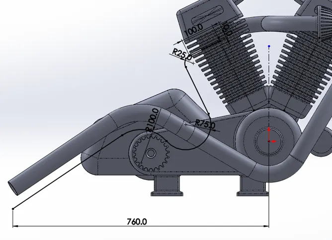
Figure 53: Sketch on the Front plane
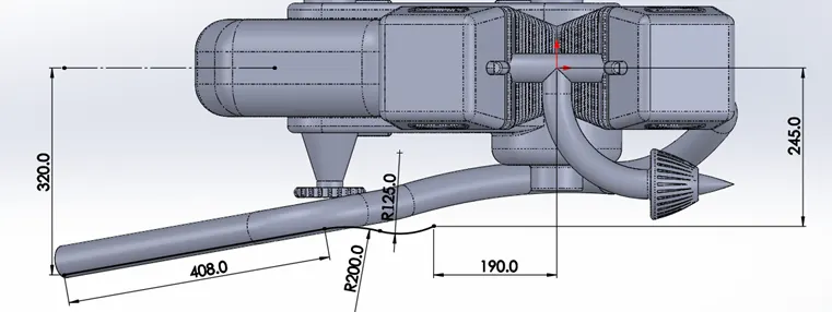
Figure 54: Sketch on the Top plane
- Project the curves using the above sketches and sketch the following sketches on the right plane and top plane respectively and then Finally project curve using two sketches.
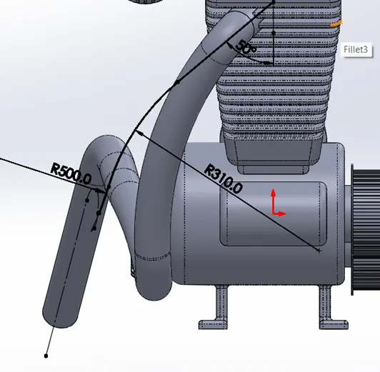
Figure 55: Sketch on the Right plane
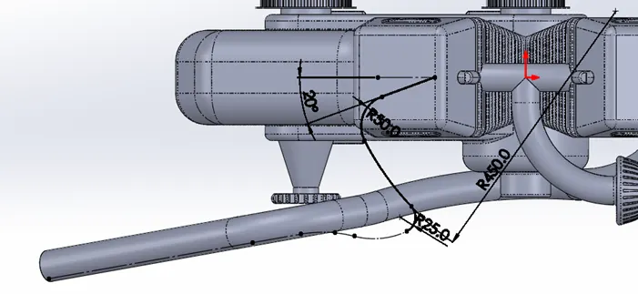
Figure 56: Sketch on the Top plane
- Create new reference plane from the upper edge and upper endpoint of the curve created and also create a composite curve from both curves created and sketch concentric circles of 50mm outer diameter with an offset of 3mm between them and pierce circle centre with the endpoint of the curve.
- Sweep the circular sketch along the composite curve as the path and sketch the line on the top plane with the following dimensions as shown in figure
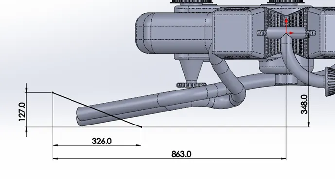
Figure 57: Sketch on the Top plane
- Use the split tool to remove the parts using the line and sketch and create the spark plug wires.
- Finally, apply an appearance on the part and save the part file.
13. Gas Tank
Gas tank is the fuel storage component of the motorcycle. It acts as the fuel reservoir for the chopper. It is connected to the fuel pump or a fuel regulator device such as carburettor or an injection system to supply appropriate amount to the engine with proper mixture of air and fuel.
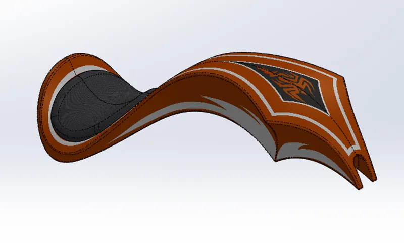
Figure 58: Gas Tank
Commands Used:
- Sketch Picture
- Transparency
- Line
- Spline
- Sweep
- Surface Trim
- Surface Loft
- Mirror
- Surface knit
- Split line
- Extrude
- Reference Geometry
- Curves
- Projected Curve
- Fillet
- Cut Sweep
- Shell
- Appearance
Procedure:
- Rename the Front plane, Top plane and right plane as Mid plane Fuel tank, Bottom plane fuel tank and Front plane fuel tank.
- Begin the sketching on the Midplane fuel tank and insert the sketch picture of the chopper with X=-2069mm and Y=-1096mm with image transparency of 0.5 and rename it as Underlay fuel tank.
- Start new sketch on the Midplane fuel tank and sketch a horizontal construction line of 831mm from the origin to its left and another vertical construction line of 441mm at the endpoint of the horizontal line.
- Continue sketching splines on the construction lines with dimensions as shown in figure.
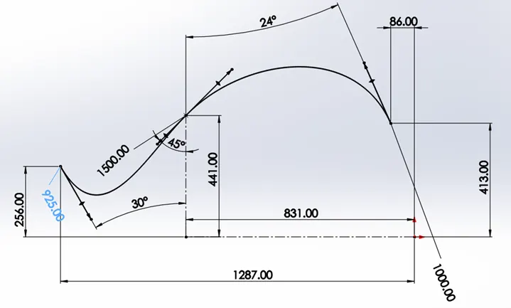
Figure 59: Sketch on the Midplane Fuel tank
- Sketch a new reference plane from the front plane fuel tank and the frontend point of the spline and sketch the following figure such that the spline constructed in it having pierce relation with the before sketch.
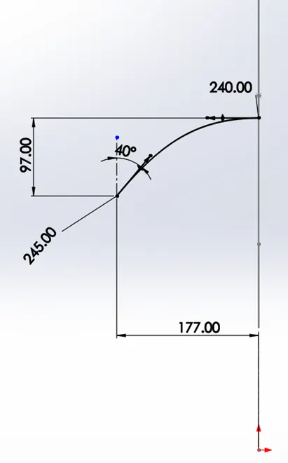
Figure 60: Sketch on the new reference plane
- Apply sweep on it with the above sketch as the profile and the midplane fuel tank as the profile path and midplane fuel tank as its direction vector.
- Select the Bottom plane fuel tank and sketch vertical line of 37.5mm from the upper right-hand point and then continue with spline and go down to the left and continue sketching with proper dimensions as shown in figure
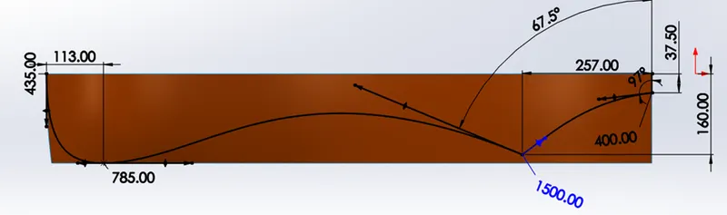
Figure 61: Sketch on the Bottom plane fuel tank
- Use trim surface and remove the outside portion that we don’t need and then create a new reference plane from the Midplane fuel tank and the frontend point of the surface.
- Sketch the following spline with dimensions on the new reference plane as shown in figure
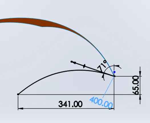
Figure 62: Sketch on the reference plane
- Begin sketching on the Front plane fuel tank and sketch a vertical construction line by bringing back the entities of the before Front plane sketch and convert them into construction and continue sketching a spline from its end point to the endpoint of the surface with dimensions as shown in figure.
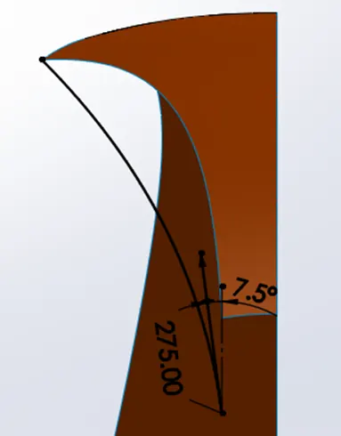
Figure 63: Sketch on the Front plane fuel tank
- Project the curve from the above sketches and create the surface loft.
- Create a new reference plane from the Front plane fuel tank and the reference point.
- Then, on the Bottom plane fuel tank sketch a horizontal construction line from the origin to its left and then continuing sketch as shown in figure
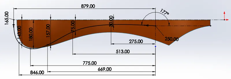
Figure 64: Sketch on the Bottom plane fuel tank
- Select the Midplane Fuel tank and select the last sketch and convert it to entities and then to construction and then sketch the spline with dimensions as shown in figure.
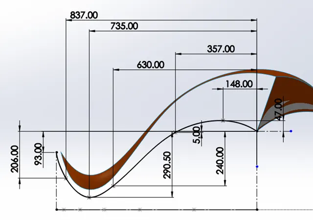
Figure 65: Sketch on the Midplane Fuel tank
- Create the projected curve from the sketches on the Bottom plane fuel tank and Midplane fuel tank and make sure the curve coincident with the surface.
- Then, sketch a line on the Midplane fuel tank such that it is intersecting between the surface and the projected curve.
- Begin sketching on the reference plane created from the Front plane fuel tank and the reference point at the back seat of the gas tank and sketch a line between the surface the projected curve.
- Use Boundary surface command and select the edges of the surface with curve created as direction 1 and select the lines sketched on the Midplane fuel tank and on the reference plane as direction 2.
- Mirror the entire bodies sketches across the Midplane Fuel tank and use knit surface command to knit all the bodies together.
- Select the Bottom plane fuel tank and select the outside edgers of the surface and apply an offset of 30mm inward and using the 3-point arc sketch it between the offset with its centre at distance of 165mm from the leftmost point of the edge.
- Finally, use Trim tool to get the sketch of the back seat as shown in figure.
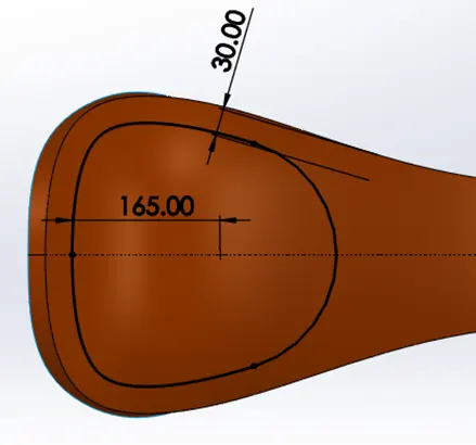
Figure 66: Sketch of the back seat on the Bottom plane fuel tank
- Use split line command by selecting the top faces of the gas tank and the above sketch. Then, use the surface extrude command with cap ends on the sketch from the top faces of the gas tank to 25mm with Bottom plane fuel tank as the direction reference.
- Apply fillet of 20mm on the edges of the seat and Use boundary surface tool on the appropriate edges as shown in figure.
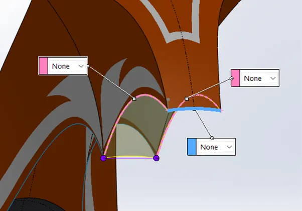
Figure 67: Selection of edges for Boundary Surface
- Use Surface loft tool by selecting the proper edges as profile and as guide curve as shown in figure.
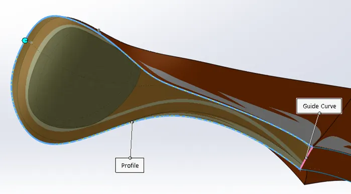
Figure 68: Selection of edges for Surface Loft
- Apply Surface knit on the complete bodies and apply fillet of 5mm on the front, back, underside edges of the gas tank.
- Begin sketching on the Midplane fuel tank and sketch a horizontal construction line at a vertical distance of 495mm from the origin and its left endpoint coincident with the reference plane created at the beginning.
- Then, continue sketching a horizontal line and spline with the dimensions as shown figure
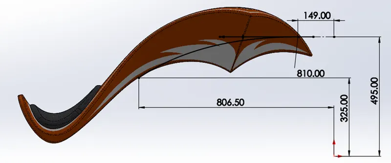
Figure 69: Sketch on the Midplane fuel tank
- Start sketch on the 1st reference plane and sketch a circle of 40mm diameter such that its centre is vertical to the origin and then sketch two vertical lines from its quadrant and horizontal line between them such that horizontal line is coincident to the origin.
- Use trim tool to remove some of the information and also use sweep cut on the sketch with the line and spline sketch above as the path.
- Apply a fillet of 2mm on the edges just cut from the tank.
- Apply shell feature of 3mm on the complete body and finally add an appearance of painted car on the complete tank and grey cotton on the seat of the gas tank.
- Finally, save the part file.
American Chopper Motorcycle Assembly:
Assembly is done in the assembly environment by inserting all the modelled parts of the chopper using insert part option. Adding component to an assembly creates a link between the assembly and the component. When SOLIDWORKS opens the assembly, it finds the component file to shown it in the assembly. Changes in the component are automatically reflected in the assembly.
The assembly of the chopper contains all the parts attached in the correct manner with proper mates. It begins with chassis been fixed and with respect to it other parts are mated.
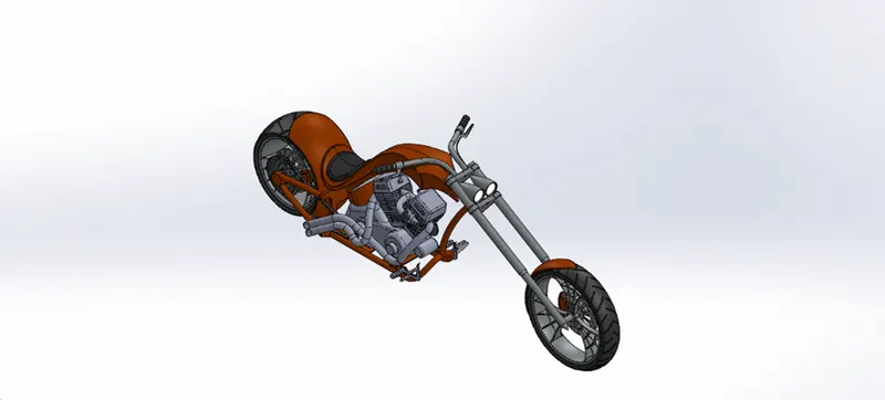
Figure 70: Assembly of American Chopper motorcycle in Isometric View
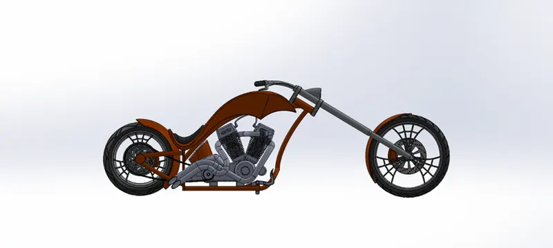
Figure 71: American chopper from Front View
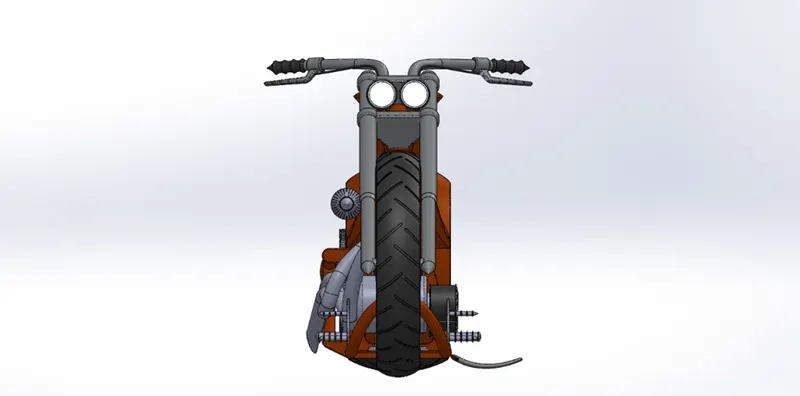
Figure 72: American Chopper from side view
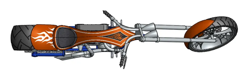
Figure 73: American Chopper Top View
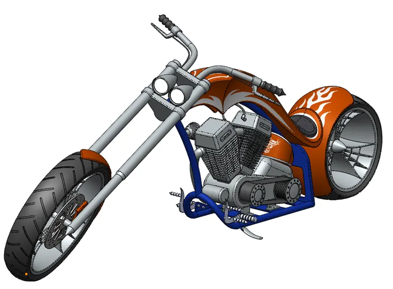
Figure 74: American Chopper from Camera view
Mates:
Mates are basically described as the geometric relation between two different components. They are 3 types of the mates used: Standard mates, Advanced mates and Mechanical mates.
- Standard Mates: Coincident, Concentric, Parallel, Perpendicular, Tangent, Lock, Mate alignment angles and distance mates.
- Advanced Mates: Profile centre, Symmetric, Path mate, Width mate, Linear/Linear coupler, Angle and distance mates.
- Mechanical Mates: Cam, Sloth, Hinge, Gear, Rack & pinion, Screw, Universal joint.
Procedure:
- Begin with new assembly file and open up all the parts file.
- Fix the chassis position such that its Midplane chassis is coincident with Front plane of the assembly.
- Next, insert the engine such that its Front plane is coincident with the Front plane of the assembly and apply coincident mate relation between the bottom support leg of the engine and the frame of the chassis.
- Along with that mate of 20mm behind the vertical face of the chassis.
- Apply concentric relation between the pedal and mounts along with it apply coincident relation between the back face of the pedal and front face of the pedal plate.
- Mirror the pedal part on the other side wit proper orientation and apply the similar relation on it.
- Apply mate relation of coincident and concentric on the appropriate faces of the kickstand with the chassis and limit angle relation on it.
- Apply coincident relation between the inner face of the transmission belt and appropriate edges of the engine and with the help of width mate relation the transmission belt centres on the component.
- Finally, apply 7⁰ angle mate on the transmission belt.
- Apply coincident relation on the Oil tank to assembly with the chassis.
- Use concentric relation between the inside of the rear wheel and the axle and also apply coincident mate between the right plane of the Wheel and Midplane of the chassis.
- Finally, apply parallel mate between the Front plane of the wheel and Right plane of the chassis to avoid any rotation.
- With proper orientation of the rear fender, apply concentric mate between the outside edges of the fender and circular edge of the rear wheel and coincident relation between the Midplane of the chassis and rear fender.
- Finally, parallel relation between the vertical plane of the fender and right plane of the chassis.
- Insert the chain and apply width mate between the inner links of the chain and sprocket of the wheel. Apply concentric and fixed relations between the chain and the sprocket. Also, apply parallel relation between the centre plane of the chain and the bottom plane of the chassis.
- Apply coincident relation between the Bottom plane of the fuel tank and the chassis and between the Midplane of the fuel tank and the chassis.
- Also apply distance mate of 5mm between the Front plane of the fuel tank and the 1st reference plane of the chassis.
- Apply concentric relation between the stem of the Front fork and the chassis and apply width mate between the faces of triple clamp and the outer sections of frame.
- Apply limit angle relation and parallel relation between the Front plane of the fork and midplane of the chassis for its movement.
- Insert the Front wheel in the assembly by applying concentric relation between the axle of the fork and the centre of the wheel and coincident relation between the Fork midplane and the centre plane of the wheel and also between the front plane of wheel and Vertical plane of the fork.
- Apply coincident relation between the vertical plane of the Front fender and Vertical plane front fork of the fork and also add coincident relation between the centre plane of the Front fender and top plane of the front wheel.
- Finally, save the assembly.
Photorealistic Rendering:
Photorealistic rendering creates high quality images or motion graphics if available so as to look appealing in various environment and backdrops. Rendering is the process of creating realistic images of the Photorealistic model with the environment. Rendering is done on two ways in Solidworks:
- Photoview 360
- It is inbuilt in SOLIDWORKS. After adding the Photoview 360, render tools can be used in SOLIDWORKS.
- Decals are added on the required faces of the chopper and by using Edit decals and appearance changes can be made.
- Various option such as Preview window, Final Render, Render region, Scene Illumination Proof Sheet, Schedule Render, recall last render can be used.
- From viewpoint- Camera and light options are used for setting up camera view and lighting of the scenes.
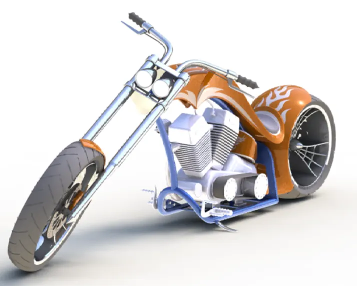
Figure 75: Render of American Chopper from the camera viewpoint
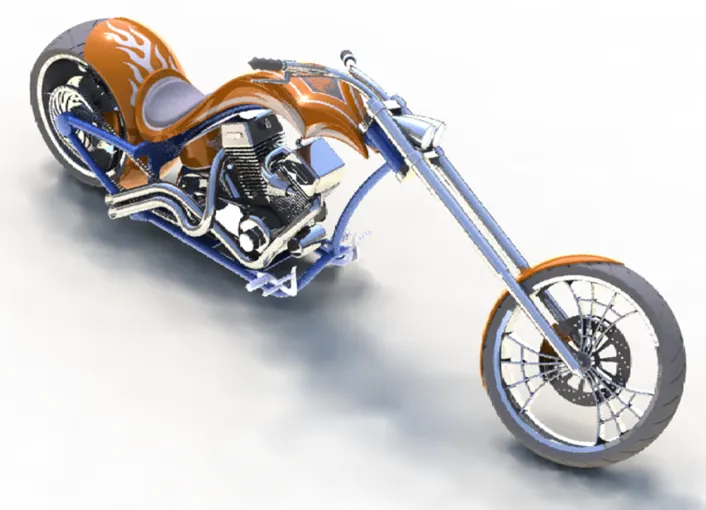
Figure 76: Render of American Chopper in Isometric View
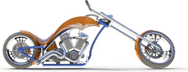
Figure 77: Render of American Chopper in Front View
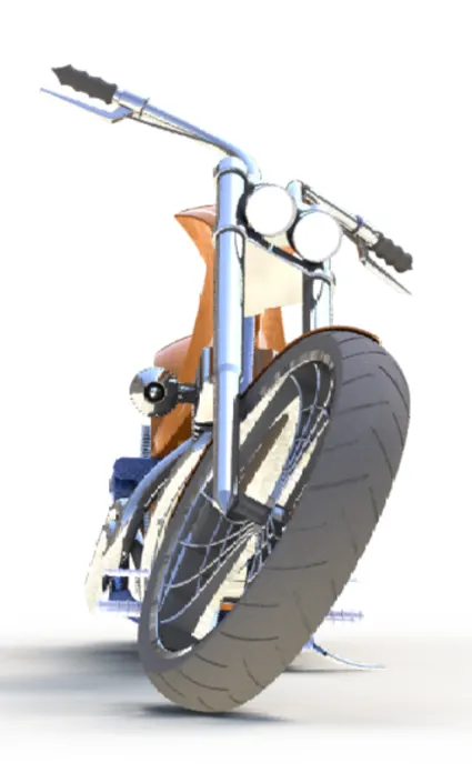
Figure 78: Render of American Chopper Side view
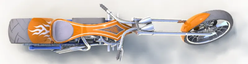
Figure 79: Render of American Chopper in Top View
2. Solidworks Visualize
- It is a separate render tool provided under SOLIDWORKS professional.
- It uses either the CPU or GPU for rendering quality images.
- Solidworks visualize quickly and easily creates professional, photo-quality images, animations and other interactive 3D contents to get your product to the product faster.
- Visualize professional adds an array of features including animations, custom lighting, VR, 360 interactives, and much more.
- Assembly file is imported and selected part appearance can be altered by using the appearance option in the appearance tab.
- Background are setup with wide range of HDR images and backgrounds from the scene tab.
- Background brightness, camera setup and lighting, rotation, gamma can be altered as required from the scenes tab.
- Camera view can be added or used from the assembly as required.
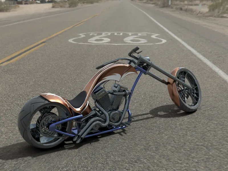
Figure 80: American Chopper on Route 66
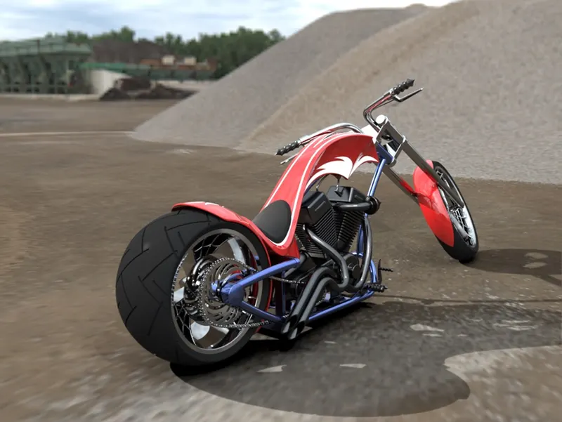
Figure 81: American Chopper on Gravel Pit
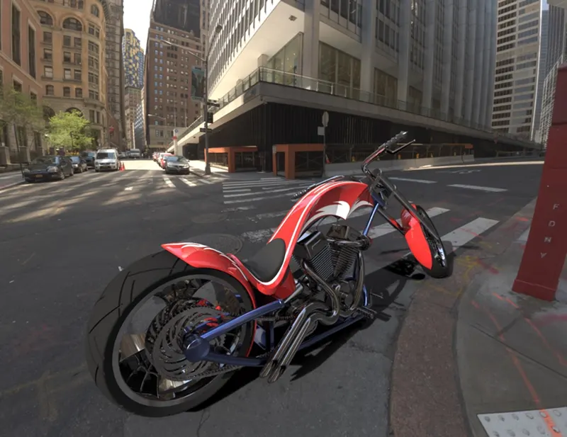
Figure 82: American Chopper on Downtown Street
Conclusion:
Design of all parts of the American chopper is done successfully using SOLIDWORKS. Assembly of all the exterior parts of the chopper is done in SOLIDWORKS assembly environment and Photorealistic rendering of the American Chopper motorcycle is successfully completed in both Photoview 360 and Solidworks Visualize.