Wiring harness design in CATIA V5 - 3D modeling Week 2 Challenge
Report of defining the given connectors and connector clip using Electrical Part design Workbench
- DT06-08SA:
In Wiring Harness Assembly Structure, to define the connector as the electrical component following Steps are to followed:
1.Firstly, 3D Connector is created or download from the resource to begin the process. We downloaded the connector from the given link.
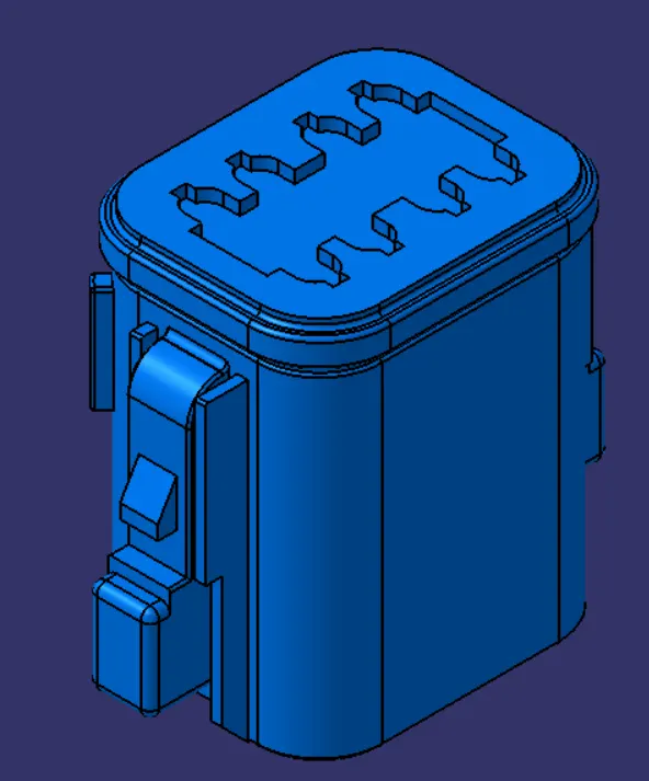
Figure: Connector-DT06-08SA
2. Next we create required geometrical parameters to define the Connector
3.Following geometrical parameters are required to define any connector:
- Connector Connection Points: The point is used for the connection of one connector to the another Connector. For the given connector, the connector connection point is created by creating a midpoint on the contact face which will be normal to wire bundle insertion.
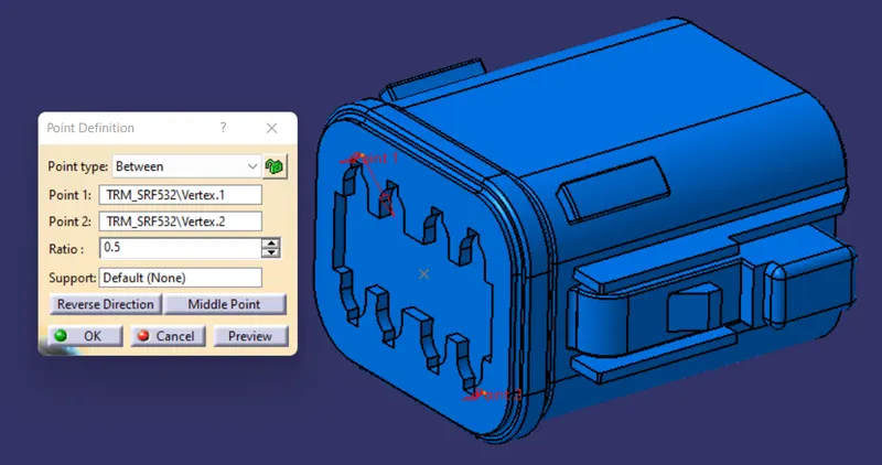
Figure: Connector Connection point
- Next, create an Axis system with respect to the point which we have created and define the axis such that the X-axis should be pointing in the direction towards the locking mechanism of the clip. The Y-axis should be pointing towards the front face of the connector. The Z- axis should be pointing across the connector from left to right.
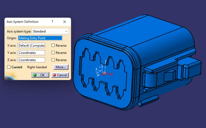
Figure: Connector Axis system
- Bundle Connection point: This point defines where the harness bundle segment point will end when routed to the elctrical connector. For the given connector, the harness bundle entry point is created on the opposite face.
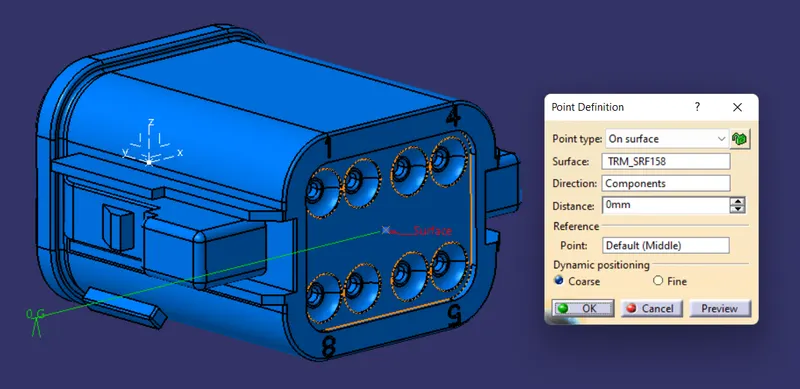
Figure: Bundle Connection point
4. Next, switch to the "Electrical Part Design" and define the given connector. Using the Connector Definition command, define the connector along with its 8 termination.
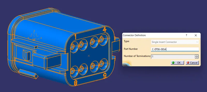
Figure: Connector Definition
5. Using Bundle Connection point command, define the Bundle connection point by selecting the appropriate face and point.
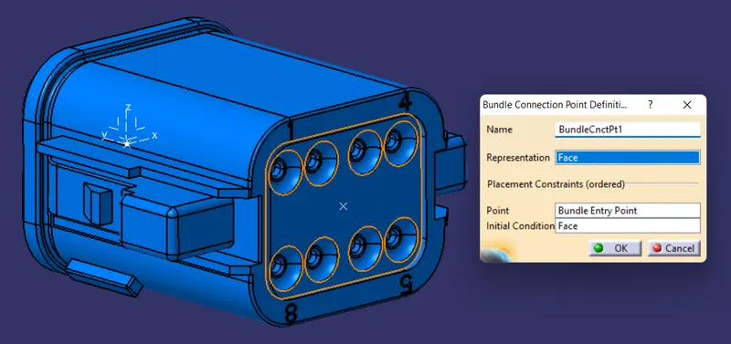
Figure: Bundle Connection point definition
6. Using Connector Connection point command, define the Connector connection point by selecting the appropraite face and point along with considering the X-axis as the orientation and the Y-axis as the coincidence.
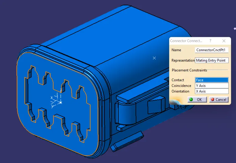
Figure: Connector connection point definition
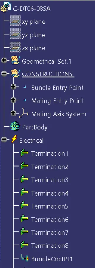
Figure: Expanded Tree (1)
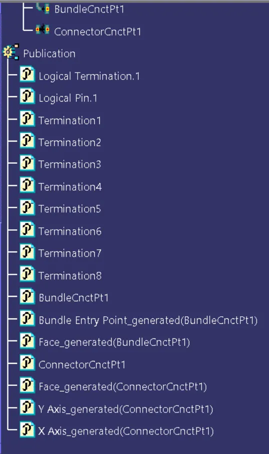
Figure: Expanded Tree(2)
174357-2:
As followed in the previous same procedure is done for defining the connector.
1. Download the connector from the given link to define the connector
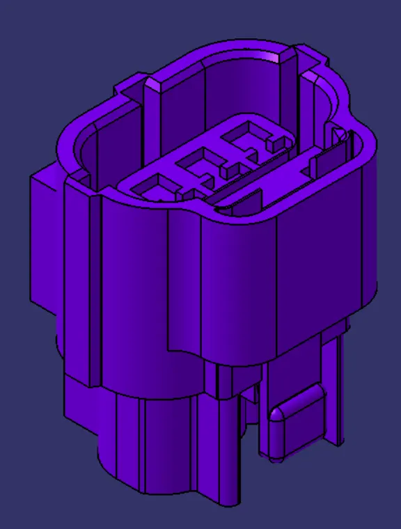
Figure: Connector - 174357-2
2. Create Bundle Connection point on the given connector as shown in figure.
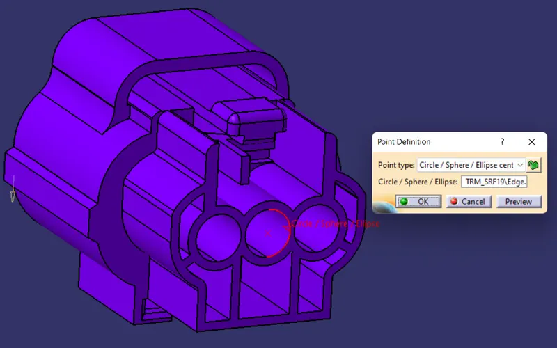
Figure: Bundle Connection point
3. Create Connector Connection point as the midpoint on the contact face which will be normal to the wire bundle insertion.
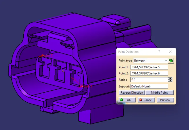
Figure: Connector Connection point
4. Next, create an axis system by defining the connector connection point as its origin and defineing the axis system such that X-axis should be pointing in the direction towards the locking mechainsm of the clip, Y-axis should be pointing towards the front face of the connector and Z-axis should be pointing across the connector from the left to right.
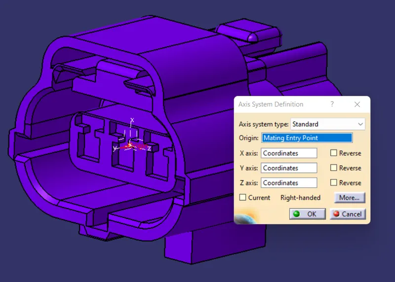
Figure: Connector Connection Axis system
5. Create Cavity connection point on the middle of the edge and create a Cavity axis system with respect to the cavity connection point with same defining method as above
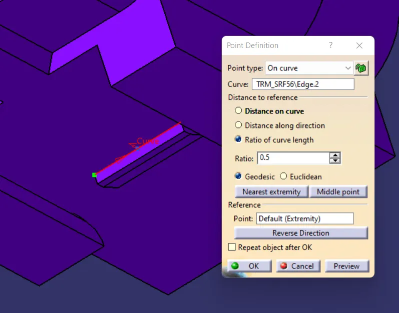
Figure: Cavity Connection point
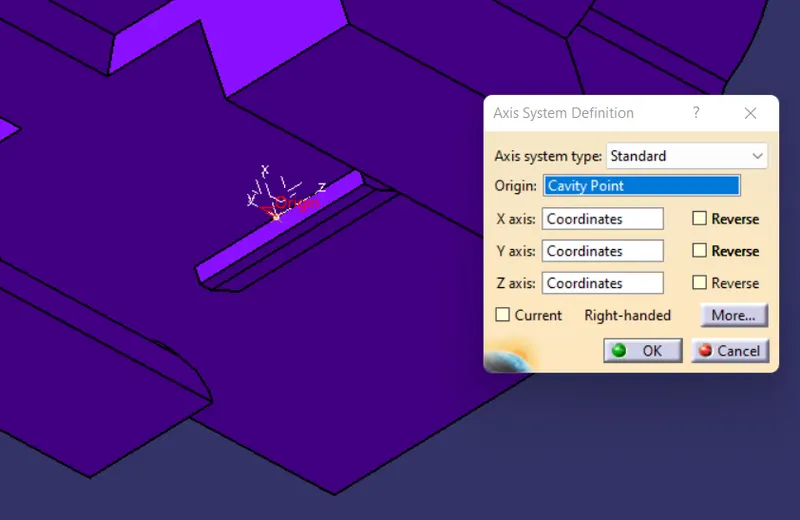
Figure: Cavity Connection point axis system
6. Next, switch to the "Electrical Part design" workbench and using the Connector Definition Command define the Connector.
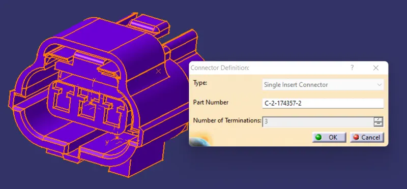
Figure: Connector Definition command
7. Using the Bundle Connection Command define the bundle connection point of the given connector by selecting the approprate face and the point
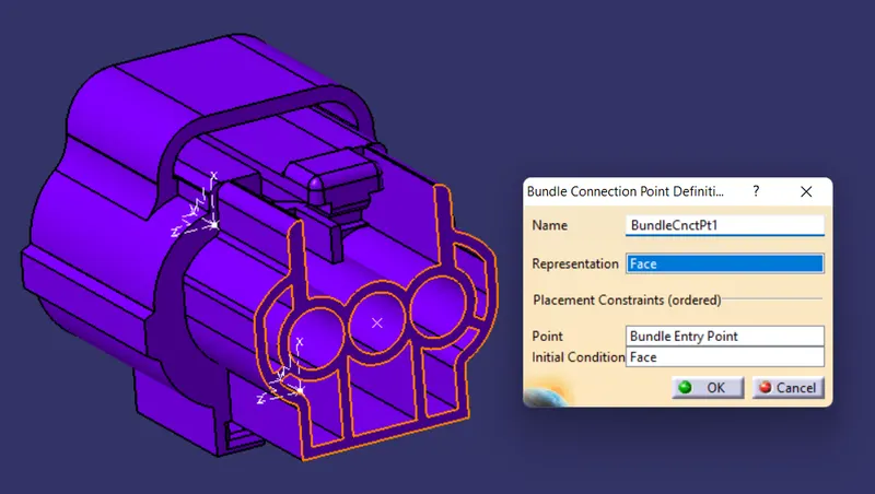
Figure: Bundle connection point definition
8. Using the Connector Connection Command define the connector connection point by selecting the appopraite face and point along with considering the X-axis as the orientation and the Y-axis as the coincidence.
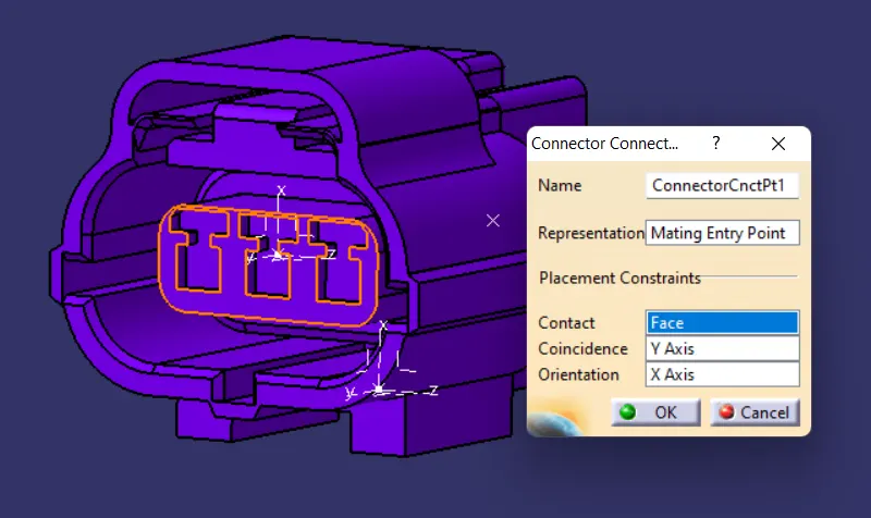
Figure: Connector connection point definition
9. Using Cavity Connection define Command, define the cavity connection point with appropraite face and point along with X-axis as the orientation and the Y-axis as the coincidence.
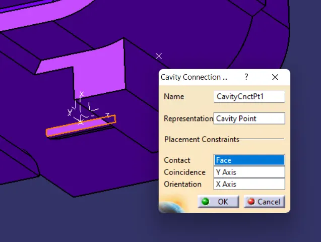
Figure: Cavity connection command
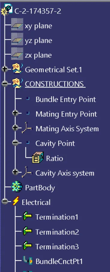
Figure: Expanded Tree (1)
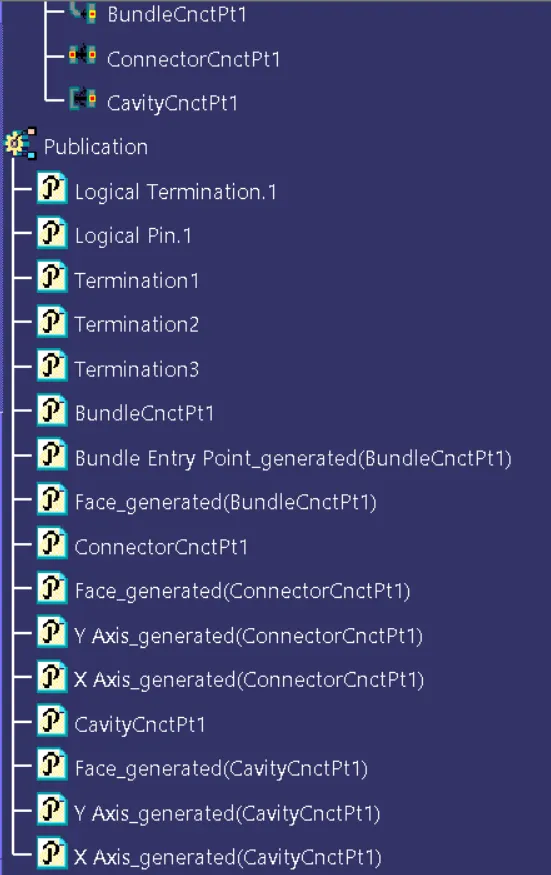
Figure: Expanded Tree (2)
- 85229-1
1. Download thre Connector clip from the link given above
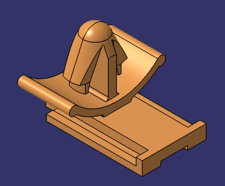
Figure: Connector Clip
2. Next, define the geometrical parameters of the conector clip by defining the Cavity point and the cavity axis system
3. Create a cavity point by creating a point on the midpoint of the edge and create cavity axis system by selecting the cavity point as the origin.
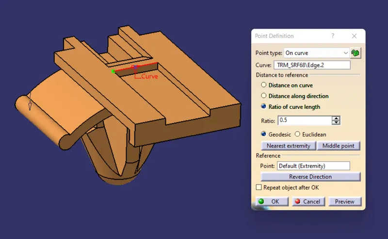
Figure: Cavity point
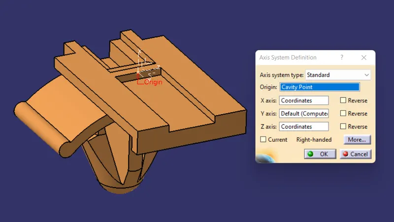
Figure: Cavity axis system
4. Next, switch to the "Electrical Part design" and define the above Connector clip using the "Mounting Equipment" Command and then using the "Cavity" Command define the connector clip by selecting the appropriate faces and the point along with axes.
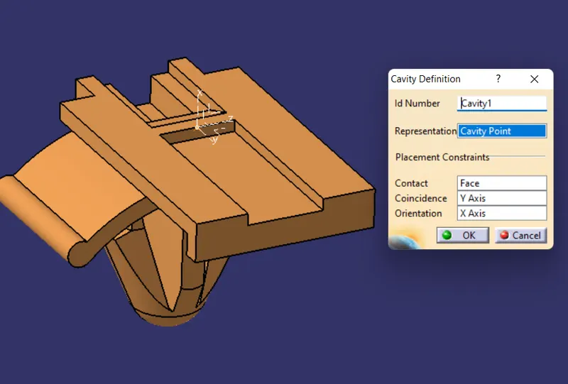
Figure: Cavity definition command
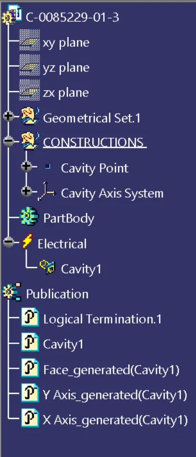
Figure: Expanded Tree of Connector clip
- Finally, Store all the documents in the catalog created. The Catalog is created by the catalog editor command under the family catalog.