Week 8 - Challenge 2 - Switch Bezel Design
Aim: To Create a Switch Bezel Component using the given Class A Surface and the tooling axis.
Report on the Draft Analysis and the Creation of the Tooling Axis
- Tooling Axis is the direction in which the mould or the core and cavity opens.
- Firstly, check visually for the best possible tooling axis and we find from the Z-direction it is most convenient.
- The base surface of the Class A Surface is extracted and a point at the centre is created and an Axis system is inserted to the point.
- Using Project intersection along the YZ plane is created and then two inclined lines are drawn inside the sketch and then bisecting line is created from the two inclined lines as the reference.
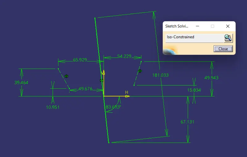
Figure: Sketch 1 on the YZ plane ( Dimensional Constraints are added to make the sketch Iso-Constrained)
- Same procedure is followed on the ZX plane but as one side inclined line is not present so a line is extruded from the centre point along Z-direction and an angle of 6⁰ is provided.
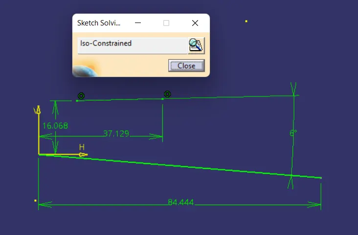
Figure: Sketch 2 on ZX Plane
- From the lines of the above sketch as the reference, the bisecting line is created and named as “Tooling Axis”.
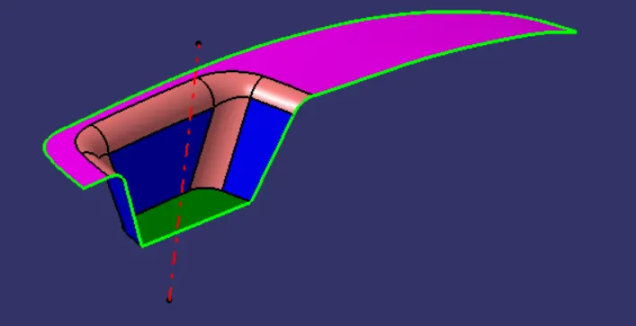
Figure: Tooling Axis on the Class A surface
- Next Draft analysis is performed on the Class A Surface by changing the view mode to custom view parameters- Matreial mode and enable the draft analysis.Then activate a compass and bring the compass on the Tooling Axis and locking on it.
- The green colour represents that the draft angle is under the nominal 3 deg.
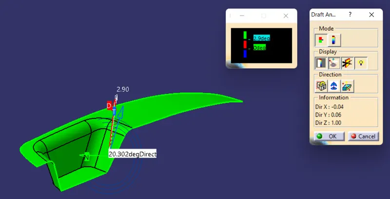
Figure: Draft Ananlysis on the Class A Surface
Creation of Class B Surface
- Required Surfaces are extracted from the Class A Surface and then Untrimmed all the surfaces
- Then surfaces are extrapolated amd required trim opreatons are performed on it.
- As the required thickness is 2.5mm then surfaces are offset to 2.5mm
- Required Corners are filleted to 12.5mm of the surfaces.
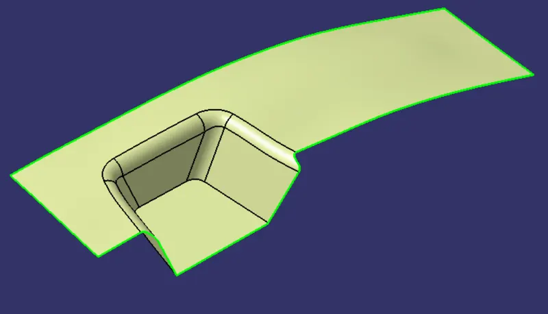
Figure: Class B Surface
Creation of Class C Surface
- Outer Edges of the Class A surface are extracted using Multiple extract command and to avoid the patches teh curve is smoothened using Curve Smooth option.
- Using Sweep Command then the surfaces are created and then they are extrapolated
- Required portion of the C- surface are trimmed out.
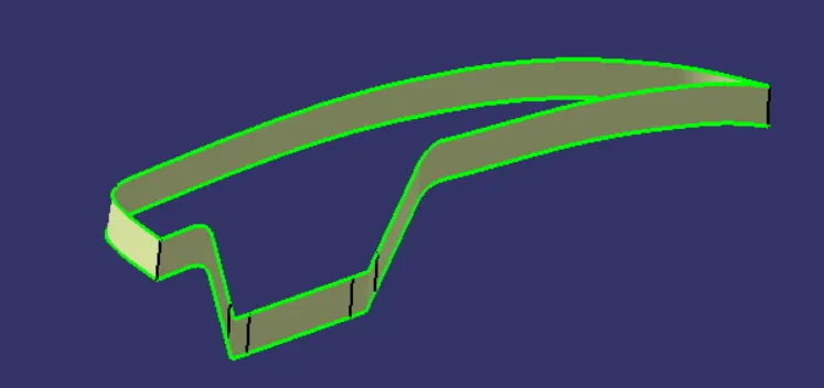
Figure: Class C surface
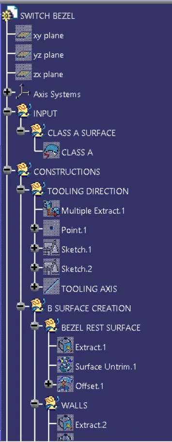
Figure: Expanded Tree (1)
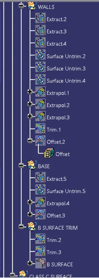
Figure: Expanded Tree(2)
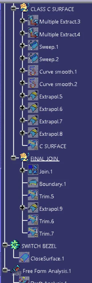
Figure: Expanded Tree (3)
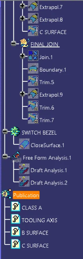
Figure: Expanded Tree (4)
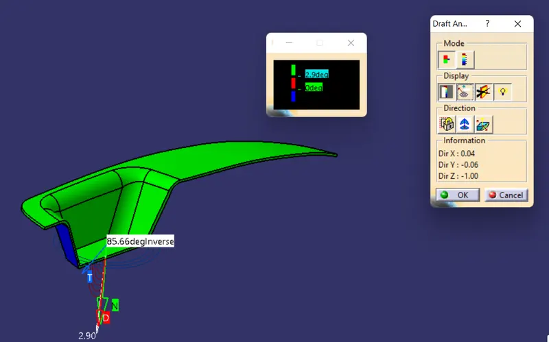
Figure: Draft Analysis of Closed Surface
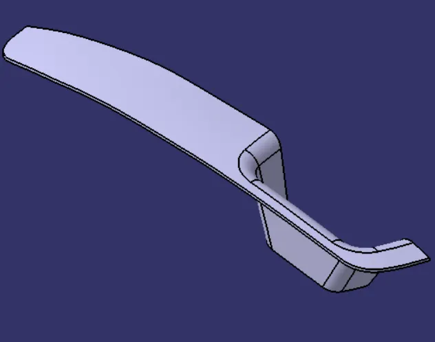
Figure: Isometric View of Closed Surface
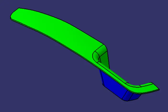
Figure: Isometric View of Draft analysis of Final Component
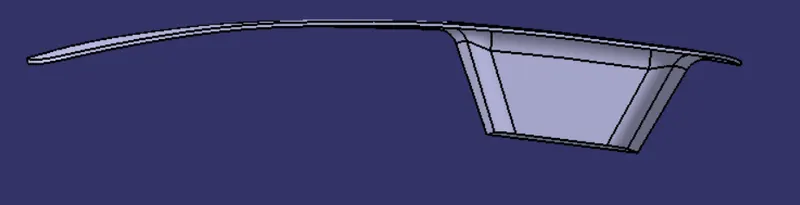
Figure: Front View of Closed Surface
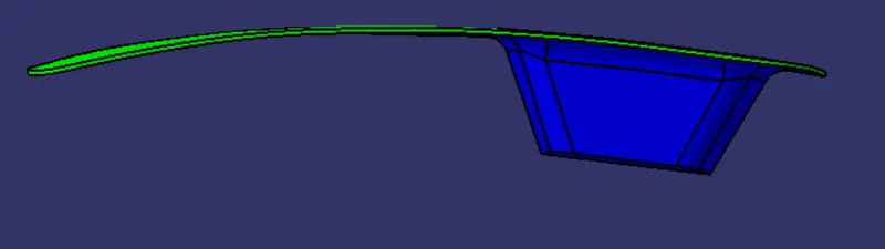
Figure: Front View of draft analysis of Closed surface
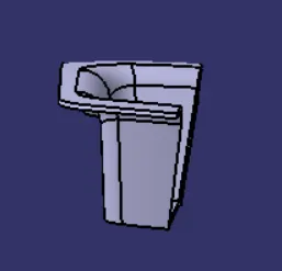
Figure: Side View of Closed Surface
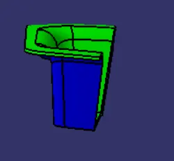
Figure: Side View of Draft analysis of Closed Surface
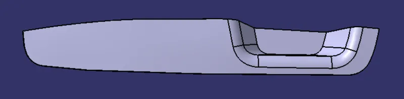
Figure: Top View of Closed Surface
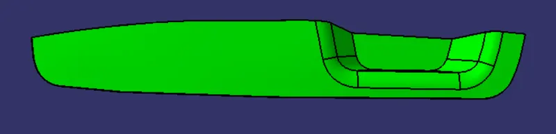
Figure: Top View of Draft analysis of Closed Surface