Week 8 - Challenge 3 - Coin Holder Design
Aim: To Create a Coin Holder Plastic Component using the given Class A Surface and perform draft analysis on Class A and Final Closed Surface.
Report on Draft Analysis and the Creation of the Tooling Axis
- Tooling Axis is defined as the direction in which the mould or core and cavity opens.
- Class A surface is imported from the given CATIA file and check the boundary of the Class A Surface.
- Extract the base of the Class A Surface and create a point at the centre of the surface as the reference of tooling axis.
- Create a normal line to the surface and considered as "Tooling Axis".
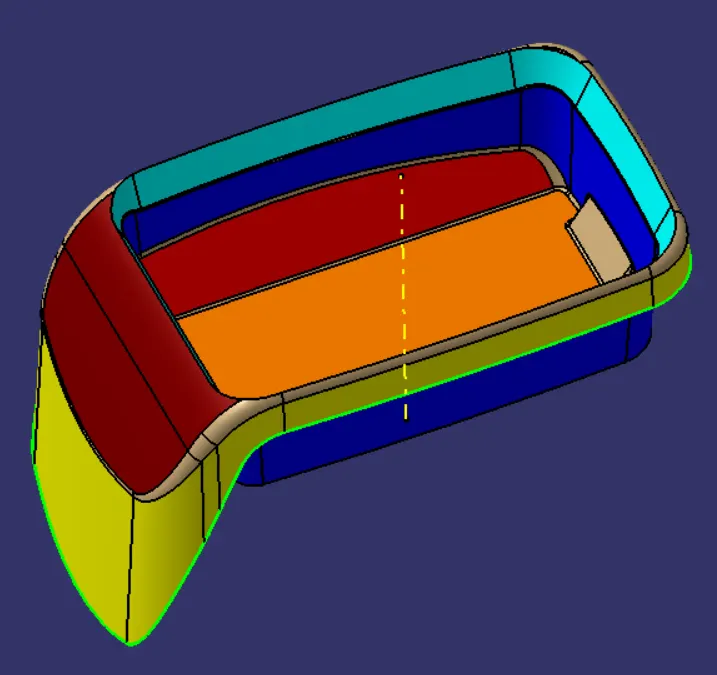
Figure: Tooling Axis on Class A Surface
- Perform Draft analysis on the Class A surface by changing the view mode to custom view parameters - Material made and enable the draft analysis. Then activate the compass and bring the compass on the tooling axis and locking on it.
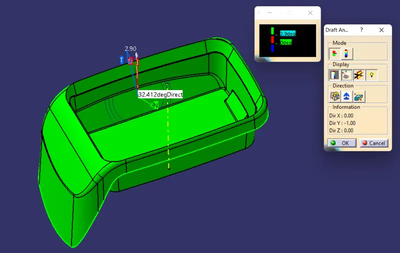
Figure: Draft Analysis on Class A surface
Creation of Class B Surface
- Side walls are extracted from the Class A surface and then surfaces are untrimmed and extrapolated.
- Next, all the surfaces are trimmed together and proper fillet are performed on them.
- Similar procedure are performed on the Base, top wall and outer flange and finally, B surface is created.
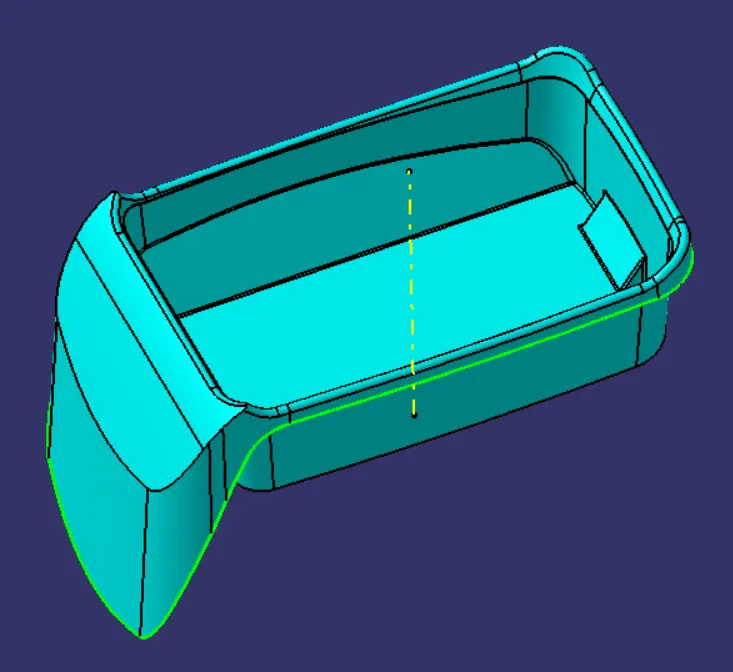
Figure: Class B Surface
Creation of Class C Surface
- Now, using the Class A surface bounday as the reference, Create the Side Wall at 90 degree of 5mm
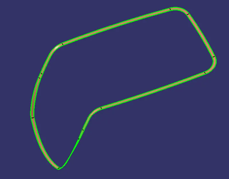
Figure: Class C Surface
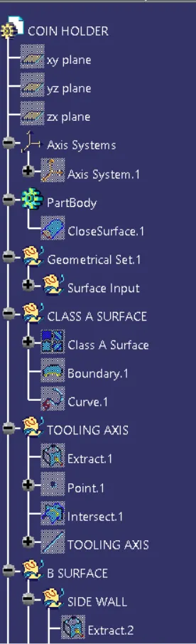
Figure: Expanded Tree(1)
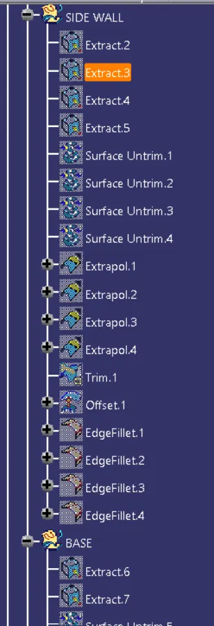
Figure: Expanded Tree (2)
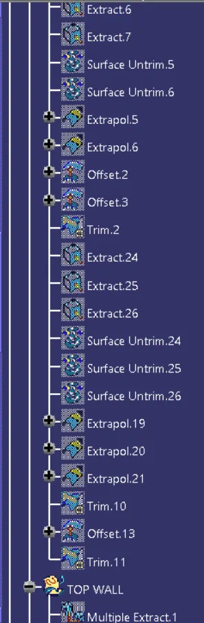
Figure: Expanded Tree (3)
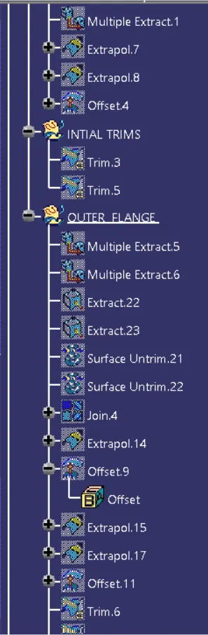
Figure: Expanded Tree (4)
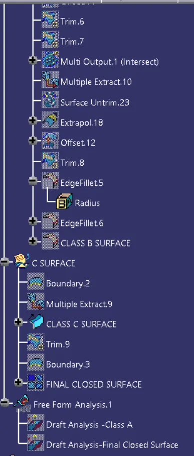
Figure: Expanded Tree (5)
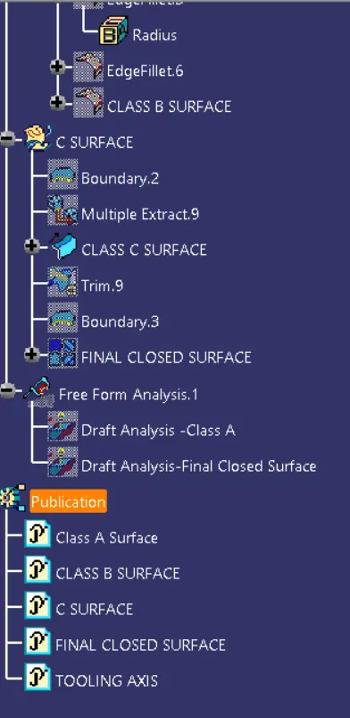
Figure: Expanded Tree (6)
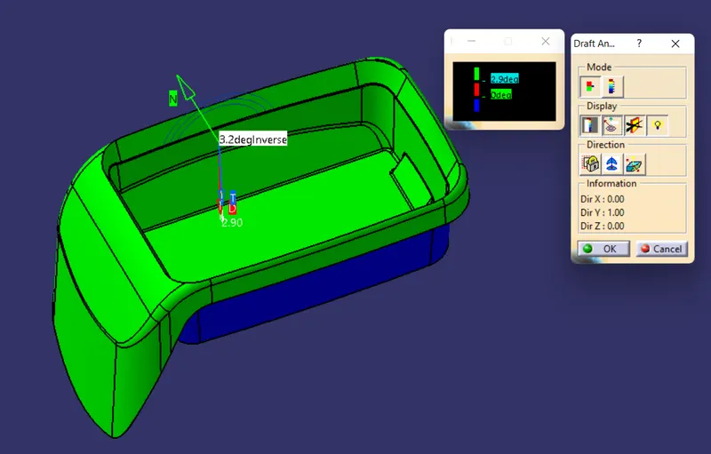
Figure: Draft analysis on Closed Surface
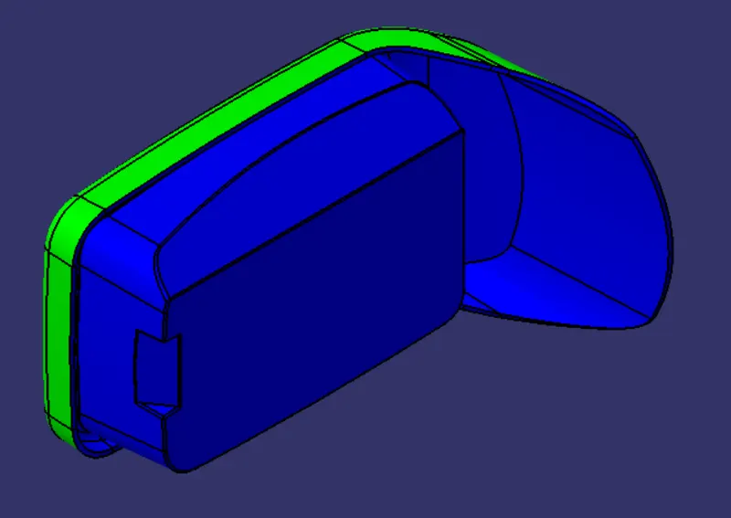
Figure: Isometric View of Draft analysis on Closed Surface
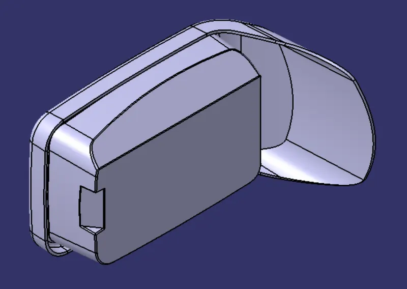
Figure: Isometric view of Closed Surface
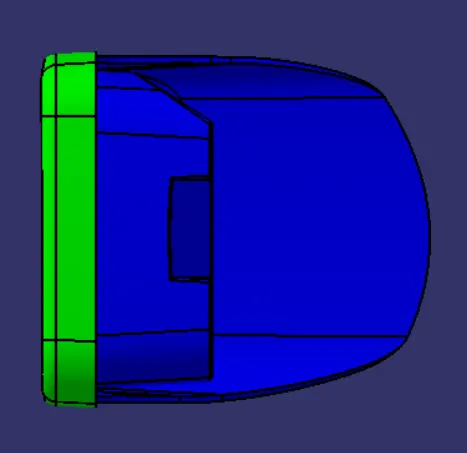
Figure: Front View of Draft analysis on Closed surface
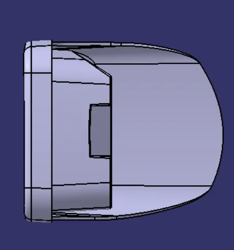
Figure: Front View of Closed Surface
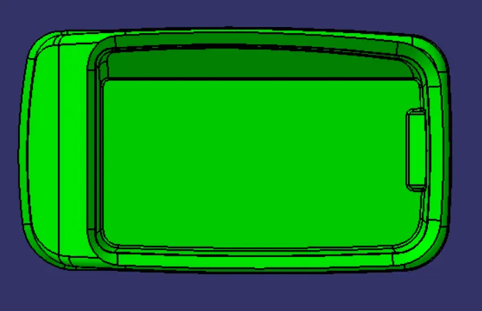
Figure: Side View of Draft analysis on Closed Surface
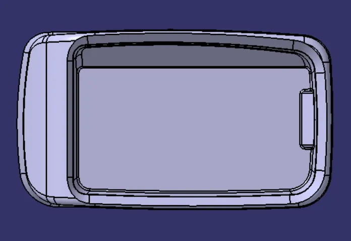
Figure: Side View of Closed Surface
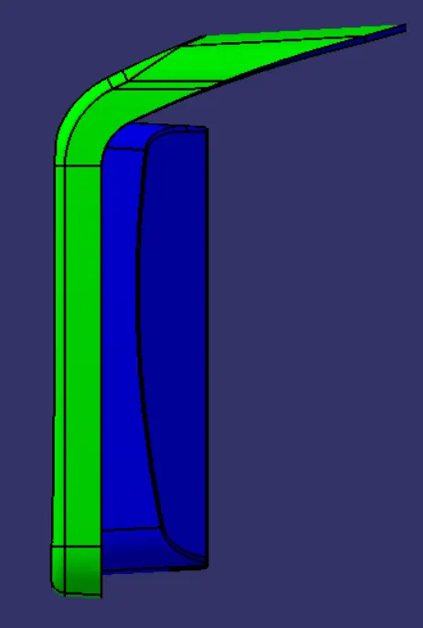
Figure: Top View of Draft Analysis on Closed Surface
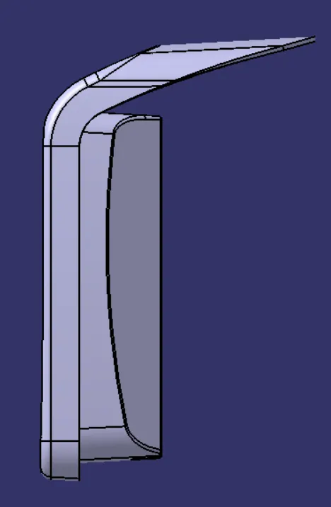
Figure: Top View of Closed Surface