Wiring harness design in CATIA V5 - 3D modeling Week 4 Challenge
Aim: To route the wiring harness in Electrical Workbench and provide the protective covering to all the branches.
Connector Definition:
- Firstly, the Connector 3D part file are downloaded from the resource
- Next step is to define the Geometrical parameters of the connectors. The required geometrical parameters are as follows
i) Connector Connection Point: This point is used for the connection of one connector to the another connector.
ii) Harness Bundle Entry point: This point defines where the harness bundle segment point will end when routed to the electrical connector.
iii) Cavity Connection Point: This point is used to define the connection of a connector to a connector clip. This only applies to the connector which have the mounting feature for a connector clip.
Connector Definition in CATIA V5
- For creating Connector Connection point, create a point on the contact face which will be normal to the wire bundle insertion.
- Next create an axis system with respect to the point which we have created and defining the axis direction such that the X-axis should be pointing towards the locking mechanism of the connector, the Y-axis should be pointing towards the front face of the connector adn the Z-axis should be pointing across the connector from left to right.
- Further create a bundle connection point on the midpoint of the face.
- Next, switch to the " Electrical Part Design " workbench
- Define the part as the connector using Define Connector Command and along with it give the number of terminations in the connector.
- Using the Bundle Connection point command define the bundle connection point by selecting the appropriate face and point.
- Using Connector connection point command define the connector connection point by selecting the appropriate face and point along with it slecting the Y-axis as the coincidence and the X-axis as the orientation.
- Same procedure is followed for all the connector to define them electrically.
- Finally, store all the Connectors in the Catalog document
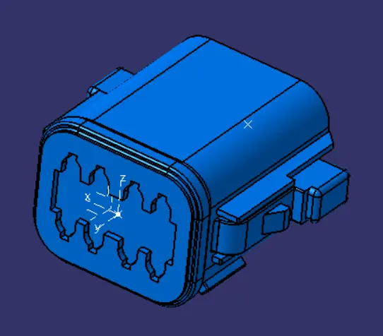
Figure: DT06-08SA
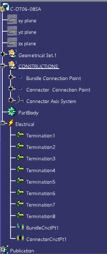
Figure: Expanded Tree(1)
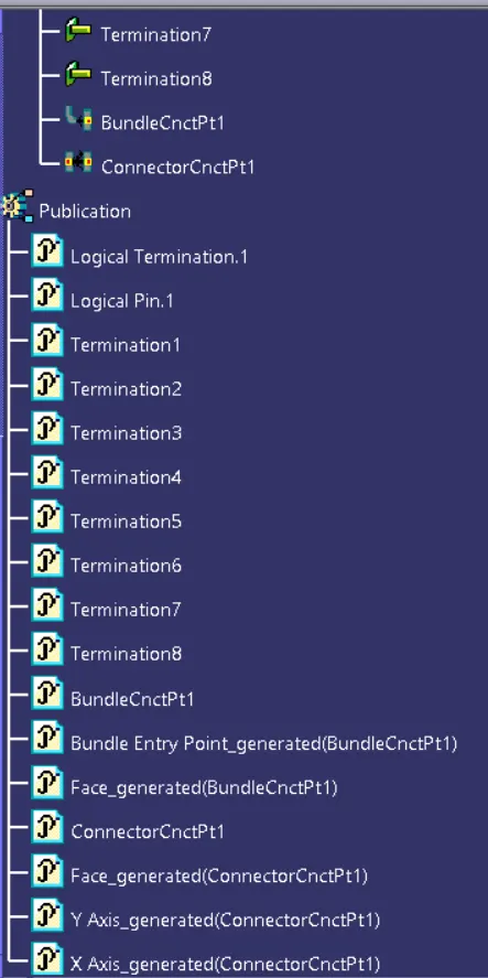
Figure: Expanded Tree (2)
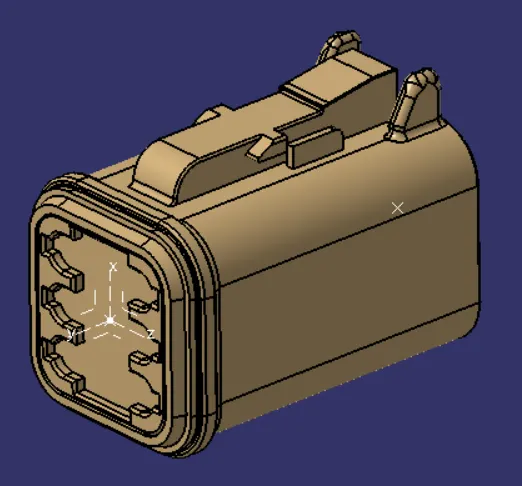
Figure: DT06-6S
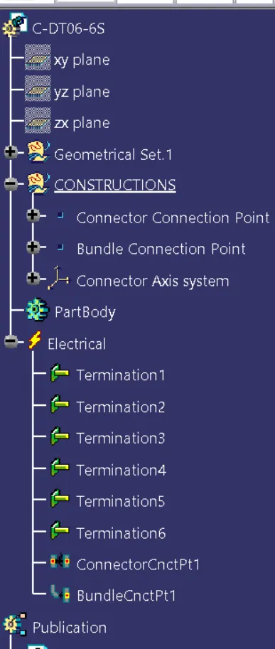
Figure: Expanded Tree (1)
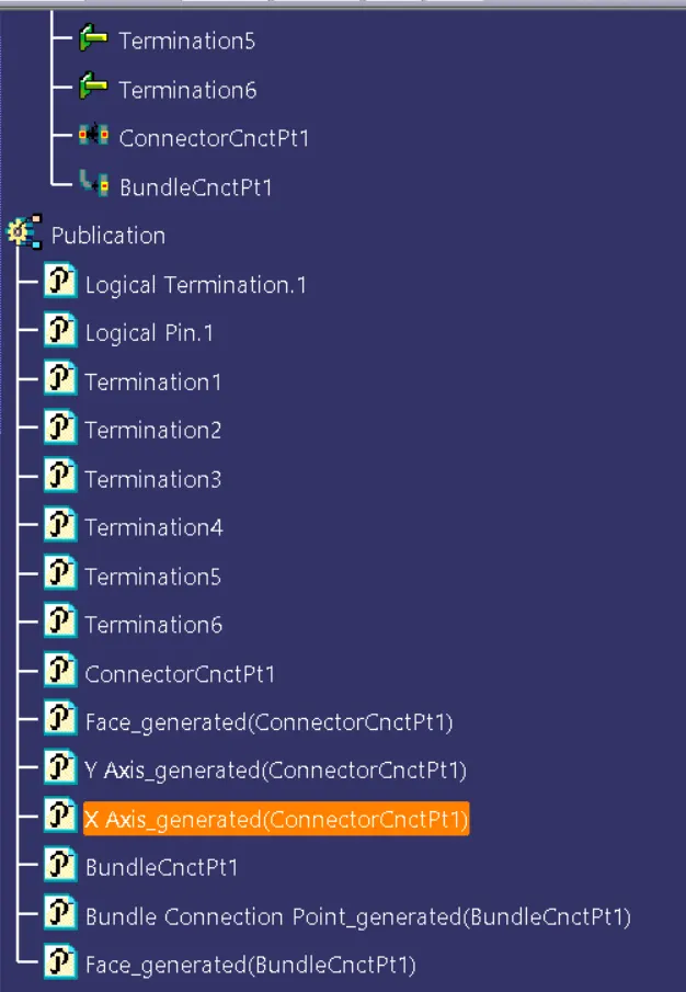
Figure: Expanded Tree (2)
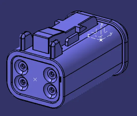
Figure: DT06-4S
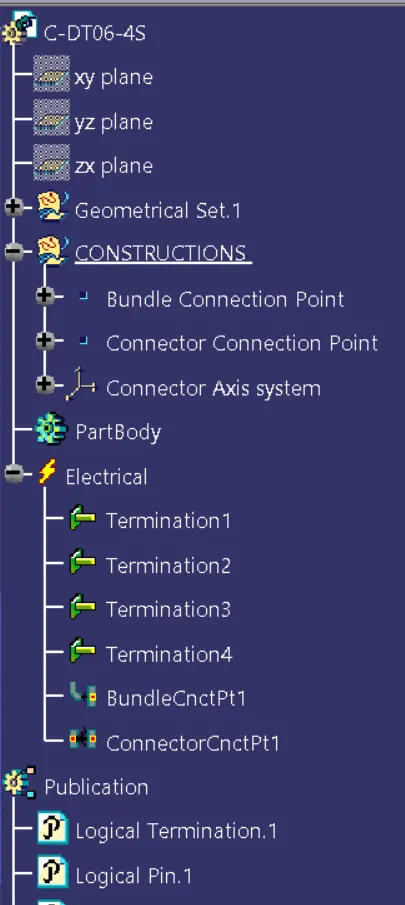
Figure: Expanded Tree (1)
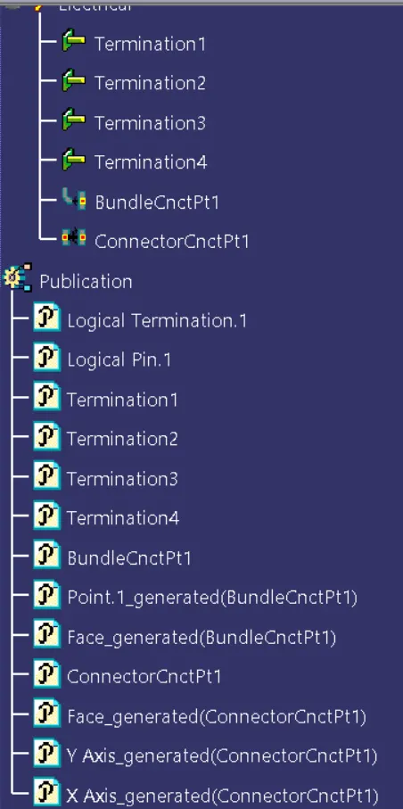
Figure: Expanded Tree (2)
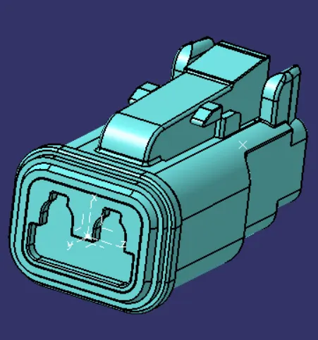
Figure: DT06-2S
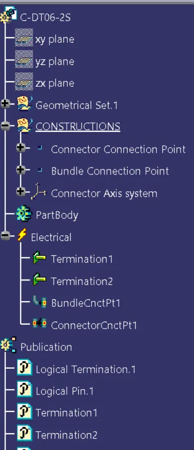
Figure: Expanded Tree (1)
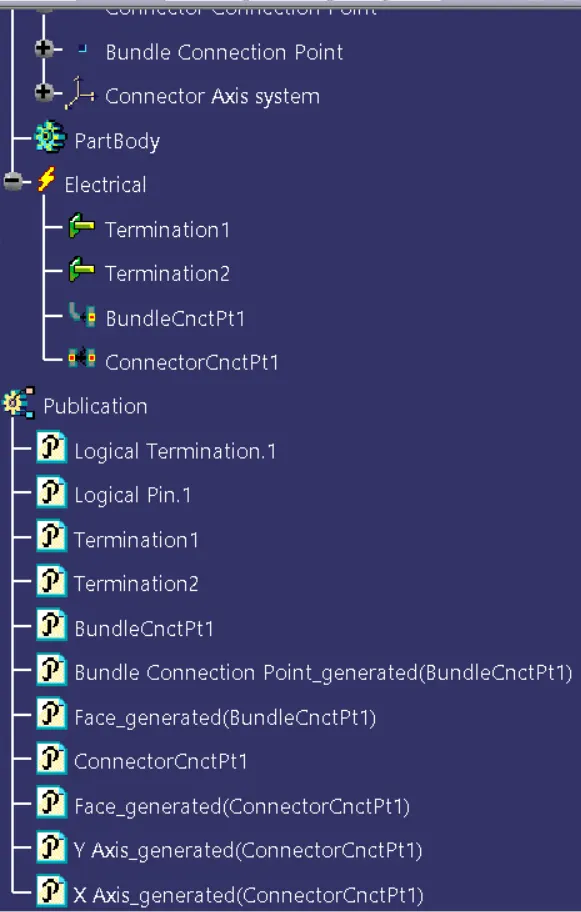
Figure: Expanded Tree (2)
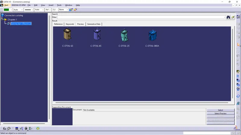
Figure: Connectors stored in Connector Catalog
After defining the componenets of Wiring Harness next we must prepare the Product assembly for the given harness.
Wiring Harness Product Assembly
Wiring Harness Product Assembly contains:
- The Harness Context Bundle: This is the top level product file that contains the harness Geometrical Bundle/Assembly and the Wire harness Electrical Bundle
- Geometrical Bundle: This sub-level product file is the wire harness product that contains all the harness components ie., clips, supports, connectors, splices, grommets, annotations and actual physical bundle segments and branches.
- Electrical Bundle: This sub-level product file contains all of the electrical circuit information.
Now create the Electric Wiring Harness context assembly and the Geometrical bundle as a subassembly containing all the electrical parameters.
- Add all the Connectors which are electrically defined already in the Geometrical Bundle assembly.
- Switch to the Electrical Harness assembly workbench and define the Geometrical Bundle assembly as electrically.
- Using the Geometrical Bundle Command define the geometrical bundle assembly electrically.
- Next to position all the connectors as given in input file create an environment on which bundle assembly will be placed.
- Create a Baseplate which is used for the bundle assembly.

Figure: Base Plate
- Next Switch to Mechanical Assembly workbench to position all the connectors on the baseplate by using the commands such as Manipulation, Snap, Smart Move and Compass commands.
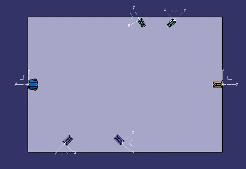
Figure: Connectors positioned on the Base plate
- Next Switch to the Electrical Harness assembly workbench and ensure that the you have your Harness Geometrical Bundle highlighted.
- Select the create Multi-Branch able Document icon.
- In the Branch definition box input all the required parameters and ensure all the bend radius ratio is set to 1.4 or greater than 1.5 and the check box is ON.
- Ensure the build mode is set to slack.
- Initially make the route definition between the connectors DT06-08SA and DT06-6S with the diameter of the bundle be as required for example 10mm as taken in this.
- Create a branch point in the Bundle segment using Add Branch point Command and add at the required length as shown in the input image and wire harness routing is done.
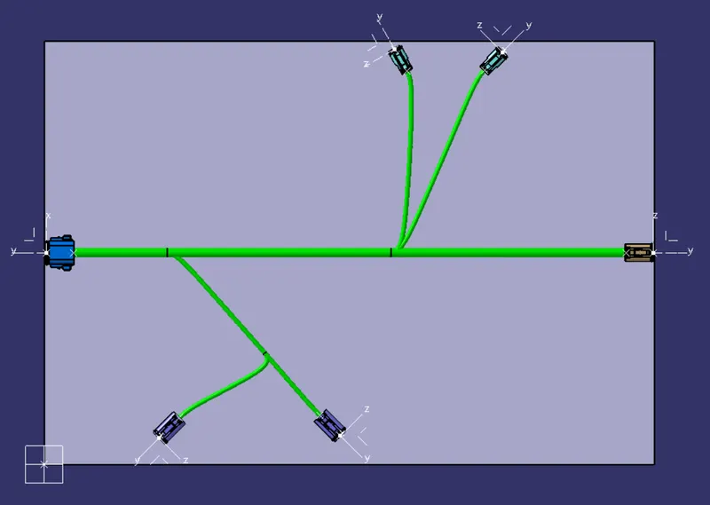
Figure: Wire harness Routing
- Now to create the protective coating on all branches switch to the Electrical Harness Assembly
- Select the Protective Covering command then select the required branch to be provided covering. Further Open the catalog of the corrugated tubes and add the appropriate corrugated tube on the bundle segment with keeping the end extremity of 30mm from the connector end and Click OK.
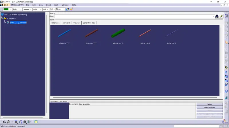
Figure: Corrugated Tubes stored in Slit COT catalog
- Follow this procedure for applying the protective covering on all the bundle segments.
- Finally, Wiring Harness routing is done.
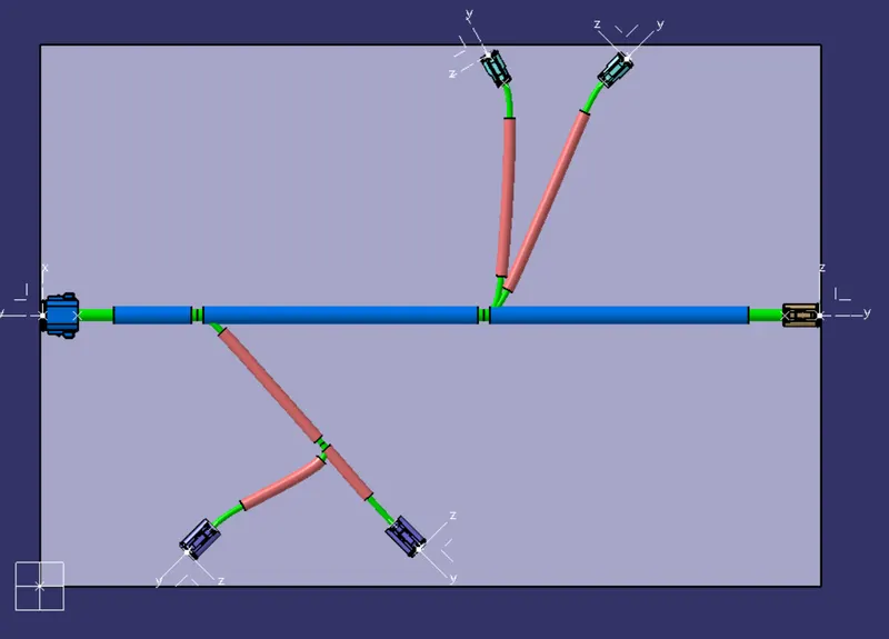
Figure: Wiring Harness Routing with Protective coating
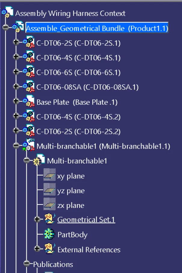
Figure: Expanded Tree (1)
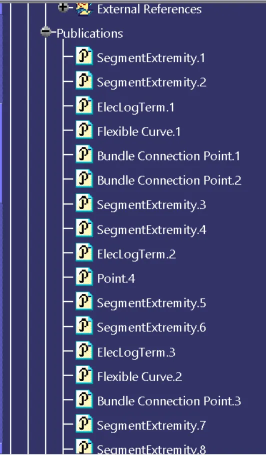
Figure: Expanded Tree (2)
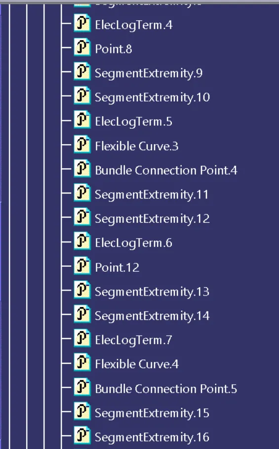
Figure: Expanded Tree (3)
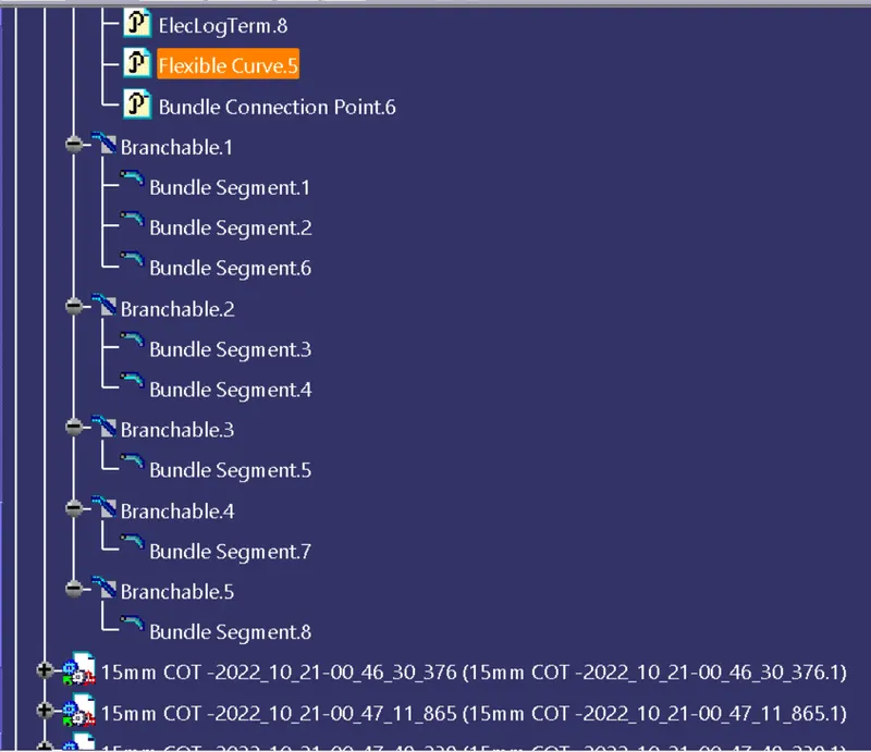
Figure: Expanded Tree (4)
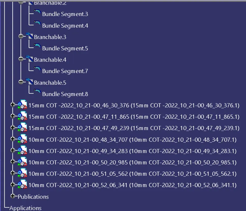
Figure: Expanded Tree (5)