Wiring harness design in CATIA V5 - 3D modeling Week 2 Challenge
Wiring harness design using CATIA V5
AIM:
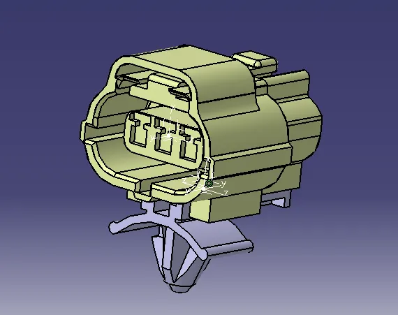
Using following connectors & Connector clip cad data from given link & define it as Electrical Connector using Electrical Part design Workbench. Define all the necessary properties to Connectors & Clip.
- Deutsch DT06 – 08SA ( https://www.te.com/usa-en/product-DT06-08SA.html)
- Tyco 174357-2 (https://www.te.com/usa-en/product-2-174357-2.html?source=header-match)
- Tyco 85229-1 – (https://www.te.com/usa-en/product-85229-1.html?q=85229&source=header)
THEORY:
Connector Definition
- Geometric properties : Points & Co-ordinate system (Axis)
- Connector connection points : This point is used for the connection of one connector to another connector.
- Harness bundle entry point : This point defines where the harness bundle segment point will end when routed to the electrical connector.
- Cavity connection point : This point is used to define the connection of a connector to a connetor clp. This only applies to connectors which have the mounting feature for a connector clip.
PROCEDURE:
Connector definitions in CATIA V5
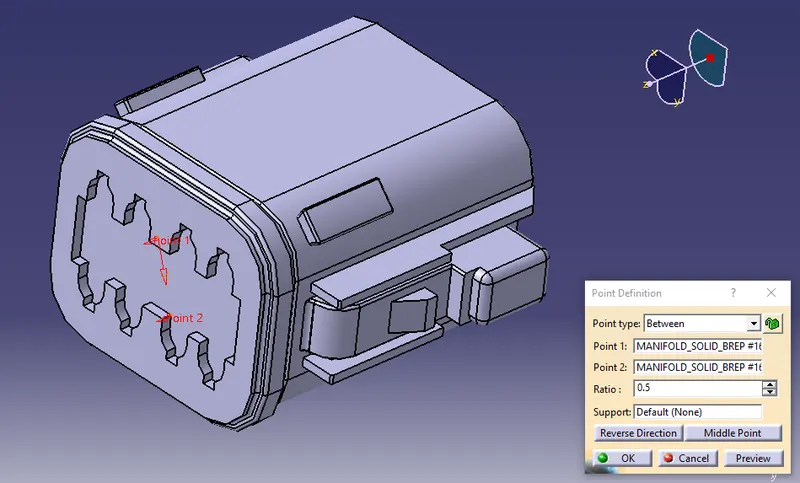
1. Deutsch DT06-08SA
Connector connection point:
- Create midpoint on the contact face which will be normal to wire bundle insertion.
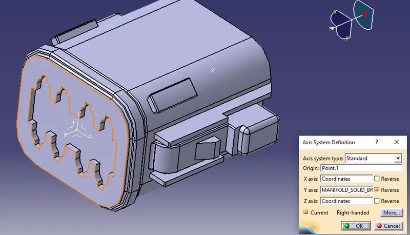
- Create an axis system at that point as origin and X,Y,Z axis accordingly.
- X towards clip locking mechanism, Y towards front face of connector and Z towards sides of connector.
- Create midpoint on the contact face which will be normal to connector insertion.
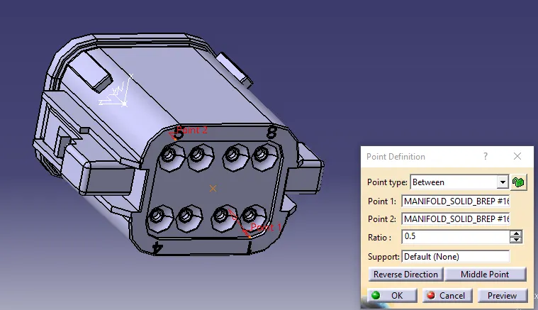
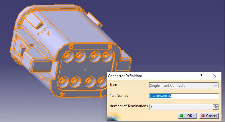
- Use connector definiton option to define connector from the stp file and number of termination according to wire supply.
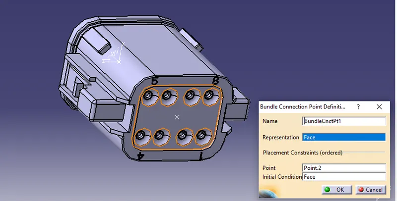
- Define bundle connection point, select the contact face, reference point and initial condition as face.
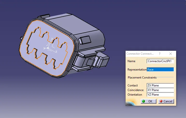
- Define connector connection point, select the contact face, contact plane, coincidence plane and orientation plane.
2. Tyco 174357-2
Connector connection point:
- Create midpoint on the contact face which will be normal to wire bundle insertion.
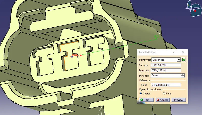
- Create an axis system at that point as origin and X,Y,Z axis accordingly.
- X towards clip locking mechanism, Y towards front face of connector and Z towards sides of connector.
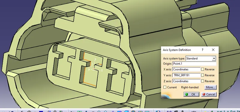
- Create midpoint on the contact face which will be normal to mounting clip insertion.
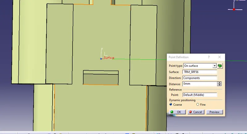
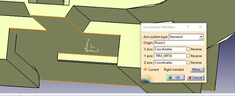
- Create an axis system at that point as origin and X,Y,Z axis accordingly.
- X towards clip locking mechanism, Y towards front face of connector and Z towards sides of connector.
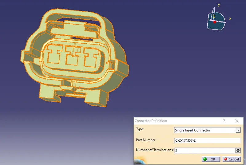
- Use connector definiton option to define connector from the stp file and number of termination according to wire supply.
- Define connector connection point, select the contact face, contact plane, coincidence plane and orientation plane.
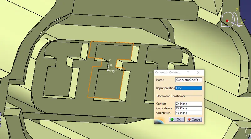
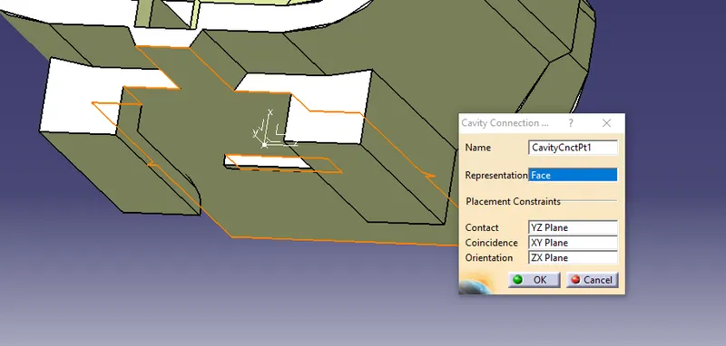
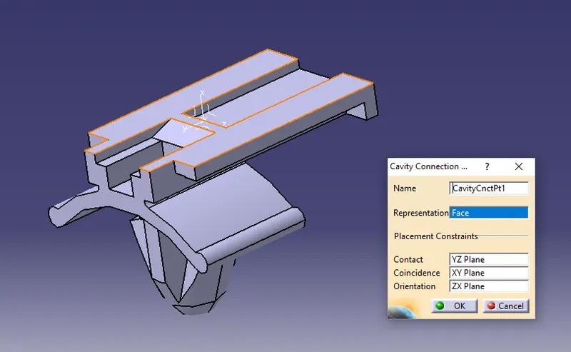
- Define cavity connection point, select the contact face, contact plane, coincidence plane and orientation plane.
3. Tyco 85229-1
- Create midpoint on the contact face which will be normal to insert mounting clip along the connector face.
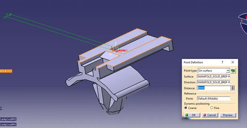
- Create an axis system at that point as origin and X,Y,Z axis accordingly.
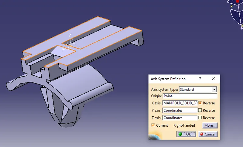
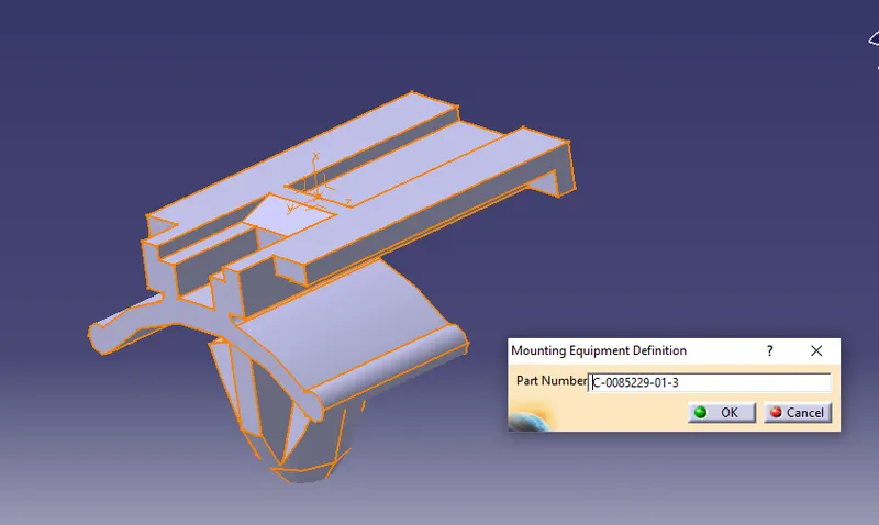
- Define mounting equipment from the stp file.
- Define cavity connection point, select the contact face, contact plane, coincidence plane and orientation plane.
- Convert to Electrical assembly design, after that import the connector and mounting clip and select connect electrical device.