Wiring harness design in CATIA V5 - 3D modeling Week 2 Challenge
Aim: Define the given connectors & connector clip as Electrical Connectors and add all the necessary properties using the Electrical Part design workbench in CATIA V5.
Objective: The goal of this project is to download the provided files from TE.com, define them as electrical connectors or equipment, and then add the necessary electrical properties to them using CATIA V5's electrical part design workbench.
The steps needed to complete this project are as follows:
- Set up the connector's necessary geometrical specifications.
- A bundle entry point should be made.
- Define a geometrical parameter for the clip if the connector can accommodate it.
- Define the part as a connector or mounting equipment.
- Establish a bundle connection point.
- A connector connection point should be made.
- If there is a clip, create a cavity connection point.
Solution:
CONNECTOR 1: Without Clip attachment[c-dt06-08sa-b-3d]
Figure 1- Defining the Geometrical Parameter to the part
Figure 2- Defining Bundle entry point
Figure 3- Defining part as a Connector
Figure 4- Defining Bundle Connection Point
Figure 5- Defining Connector Connection Point
CONNECTOR 2: With Clip attachment[c-2-174357-2-e-3d]
- Create midpoint.
- create a Connector connection point.
- create a Connector connection axis system.
- create a cavity connection point.
- create a cavity connection axis system.
- Switch to an Electric part design and define the part as a connector.
- Define the Connector connection point and cavity connection point.
Figure 1- Defining the Geometrical Parameter to the part
Figure 2- Defining Bundle entry point
Figure 3- Defining the Geometrical Parameter for clip or cavity attachment
Figure 4- Defining part as a connector
Figure 5- Defining Bundle Connection Point
Figure 6- Defining Connector Connecting Point
Figure 7- Defining Cavity Connection Point
CLIP: [c-0085229-01-a-3d]
- Create midpoint.
- create a cavity connection point.
- create a cavity connection axis system and the orientation should be the same as in the connector.
- Switch to an Electric part design and define the part as Mounting Equipment.
- Define cavity connection point.
Figure 1- Defining the Geometrical Parameters of the part
Figure 2- Defining part as mounting equipment (clip)
Figure 3- Defining Cavity
CLIP AND CONNECTOR ELECTRICAL ASSEMBLY:
- Import Connector and cavity/mounting clip.
- Select Defining Electric connection.
- select cavity and then connector.
Creating Catalogue file:
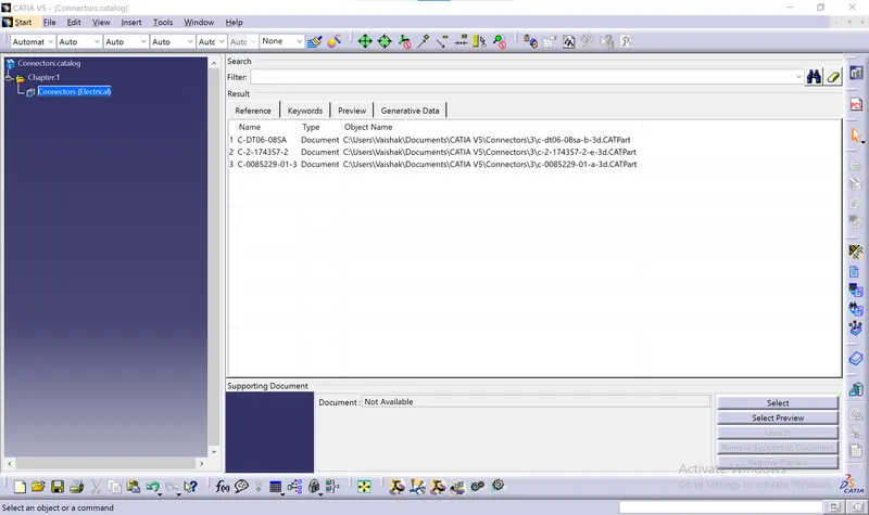
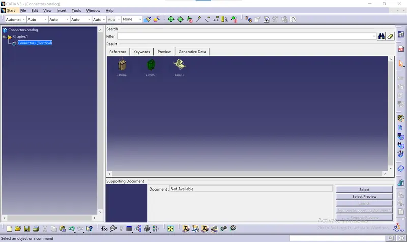
- File->New->CatalogDocument
- Add family by selecting add family tab and giving the family name and type.
- Save the catalog and add the components to it by selecting Store book.
CONCLUSION:
The connectors and the clip were both classified as electrical mounting equipment and electrical connectors, respectively. The components were given all the essential geometrical and electrical qualities.
REFERENCE:
- Deutsch DT06 – 08SA ( https://www.te.com/usa-en/product-DT06-08SA.html)
- Tyco 174357-2 (https://www.te.com/usa-en/product-2-174357-2.html?source=header-match)
- Tyco 85229-1 – (https://www.te.com/usa-en/product-85229-1.html?q=85229&source=header)