Wiring harness design in CATIA V5 - 3D modeling Week 2 Challenge
Wiring harness design using CATIA V5
Wiring harness is an assembly of various wires , equipments and connectors supported by various clips and other mounting accesories . In our context we will keep our focus on automotive wiring harness design.
CATIA
It is a very powerful 3d modeling and simulation tool that is used for generating mechanical parts, assembly, manufacturing simulation , electrical parts and assembly etc.
In this module we will be using pre-existing models of connectors and clips and use them in our assembly.
These models are there in (*.stp) format , before declaring them as electrical models we will define some parameters like points ,axis and planes for the part .
Steps to generate electrical part using electrical part design work bench
Step 1 – Download the required stp files from the links provided with the assignment
Step 2- Open CATIA- go to files – open – select the stp file from the location and press OK
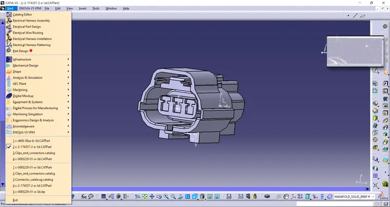
Step 3 - go to part design work bench
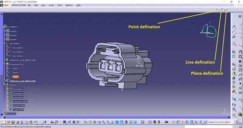
Step 4 - Define the point on the model at appropriate location using the point defination command .
Step 5- Click Insert - axis system - Insert axis system at the appropriate point as required
note - while inserting axis follow a uniformity and follow one single rule to declare the axis eg- always put y axis normal to the surface containging the point and away from the plane .
Step 6 - Go to start- equipment and system - electrical harness discipline - electrical part design
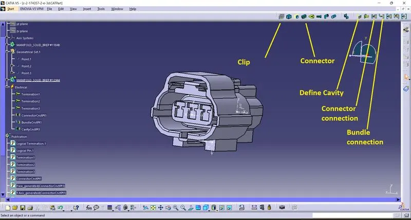
Step 7 - Inside the electrical part design work bench 1st define the component as clip/connector in clip define the geometrical constraints using the points and axis defined in part design work bench for connector - define the no of connections and press ok.
Step 8 - Define the connector and bundle connection point using the points and axes
Step 9 - Cavity and Cavity connections is required for parts with respective features .