Wiring harness design in CATIA V5 - 3D modeling Week 4 Challenge
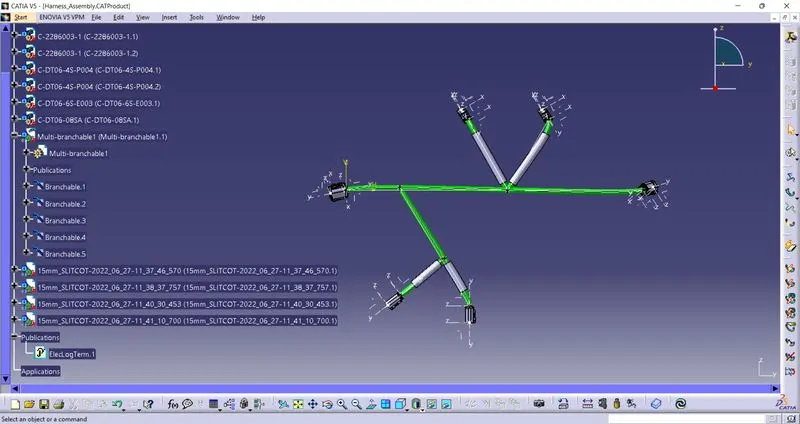
Step-0
Download all the connectros from te.com
Step-1
Open the step file in part design work-bench and declare all the required points, planes and axes
Step-2
Open the part design work bench and crerate one base sketch for the layout
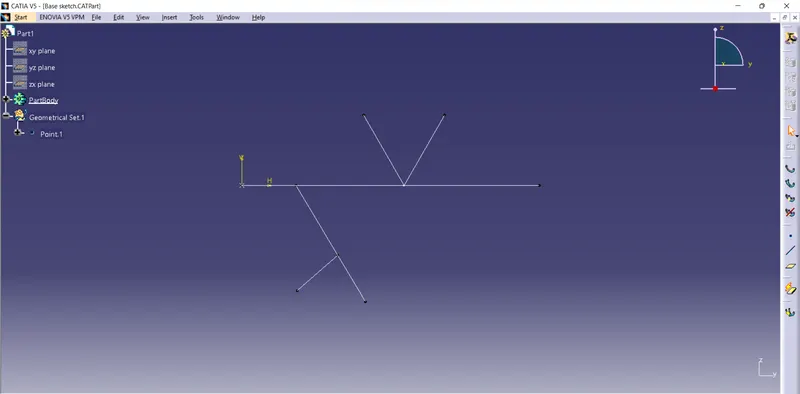
Step-3
right click on the product file and add existing components to add the connectors
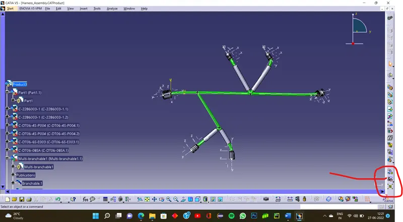
Step-4
Use the snap option to place the components at the desired points on the base sketch
Step-5
Save the file and enter the electrical harness assembly workbench
Step-6
Click on add geometrical bundle and click on product file in model tree
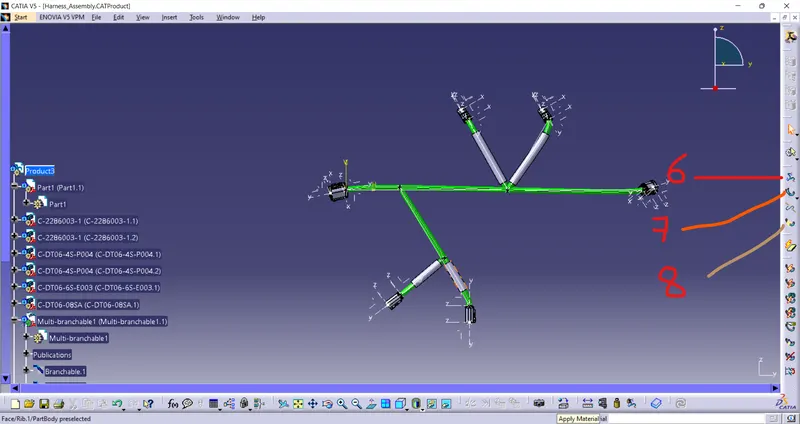
Step-7
Add the multibranchables to define the bundle and route defination
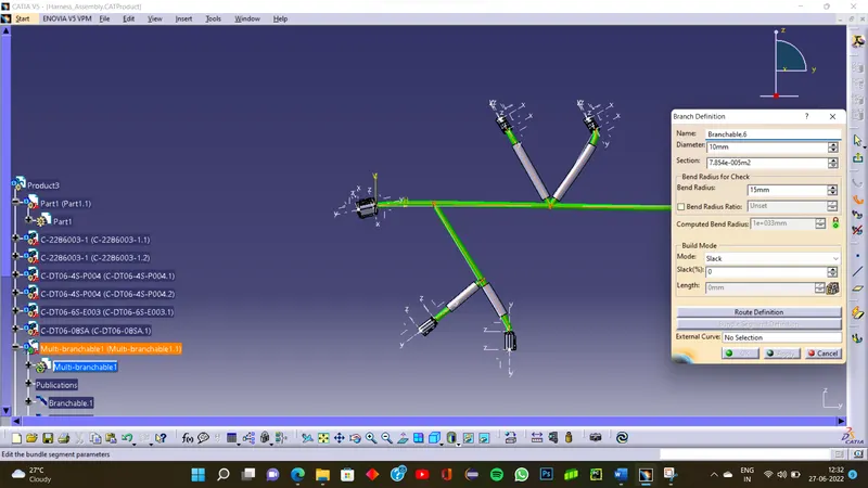
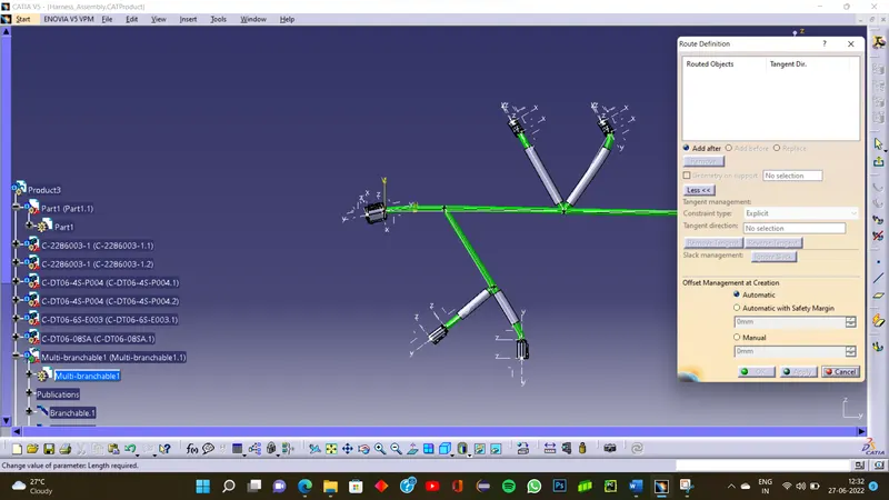
Step-7.1
Selec the 2 connectrs and press apply and okay to generate the bundle between them
Step-7.2
Add branch points into the bundle as per the layout provided.
Step-8
Add the protection coverings on the branches asked in the question