Wiring harness design in CATIA V5 - 3D modeling Week 2 Challenge
Wiring harness design in CATIA V5 - 3D modeling Week 2 Challlenge
AIM:
Download following connectors & Connector clip cad data from given link & define it as Electrical Connector using Electrical Part design Workbench. Define all the necessary properties to Connectors & Clip.
- Deutsch DT06 – 08SA ( https://www.te.com/usa-en/product-DT06-08SA.html)
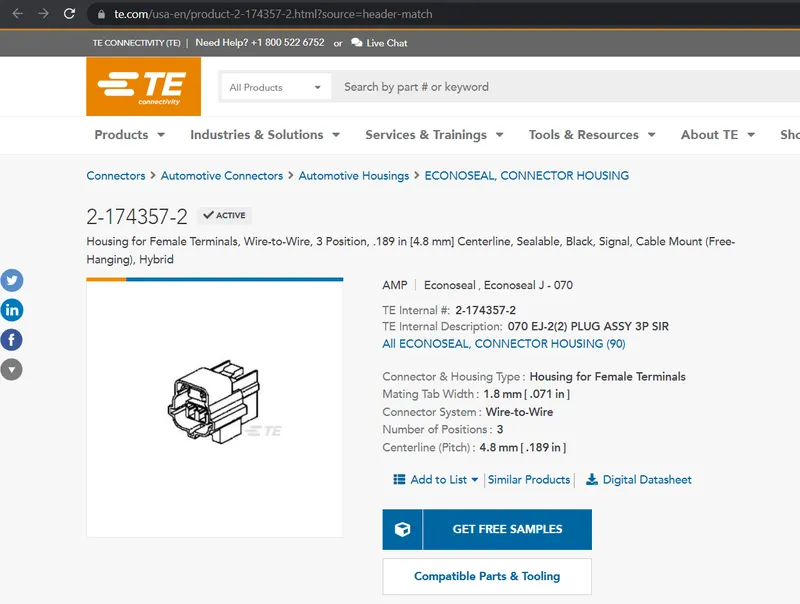
- Tyco 174357-2 (https://www.te.com/usa-en/product-2-174357-2.html?source=header-match)
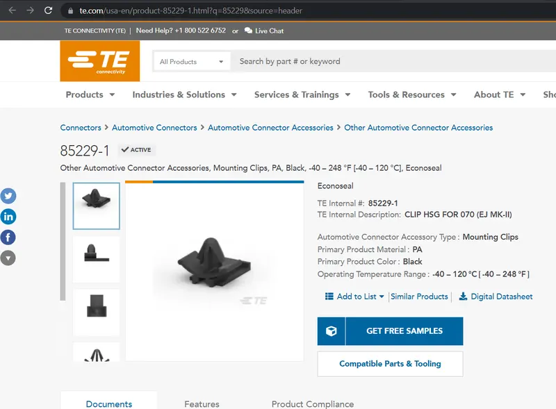
- Tyco 85229-1 (https://www.te.com/usa-en/product-85229-1.html?q=85229&source=header
INTRODUCTION TO WIRE HARNESS
Components of anelectric circuit are electrically connected if an electric current can run between them through anelectrical connector. An electrical connector is an electromechanica ldevice used to create an electrical connection between parts of an electrical circuit, or between different electrical circuits, thereby joining them into a larger circuit.Most electrical connectors have a Gender– i.e. the male component, called a plug, connects to the female component, or socket. The connection may be removable (as for portable equipment), require a tool for assembly and removal, or serve as a permanent electrical joint between two points.
Downloading all the componenets from the tyco electric website
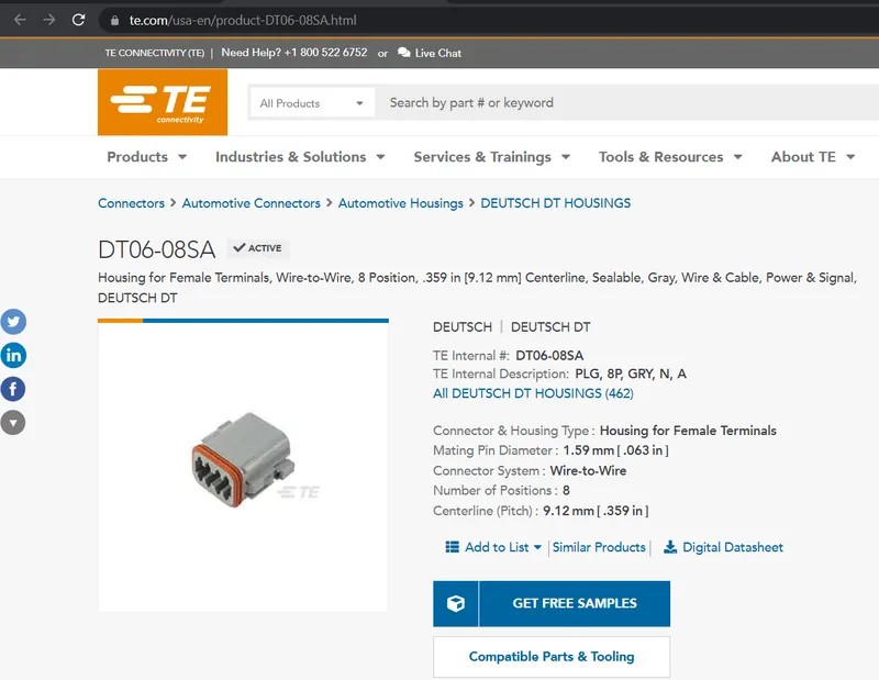
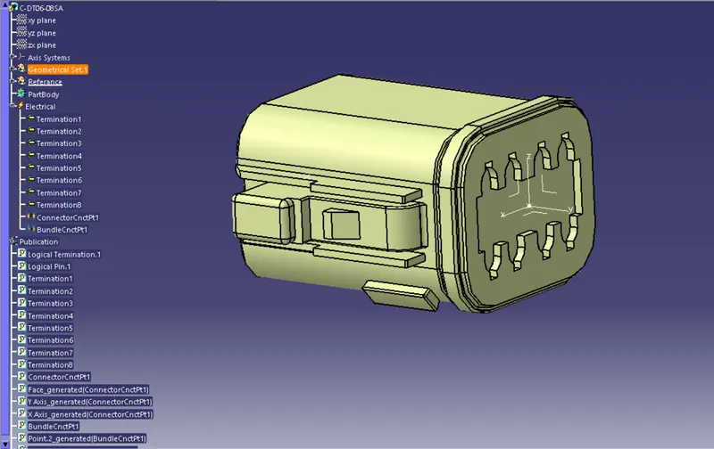
- After importing the models each part should be edited with parameters like point and Axis system.
- Then part is defined as a connector.
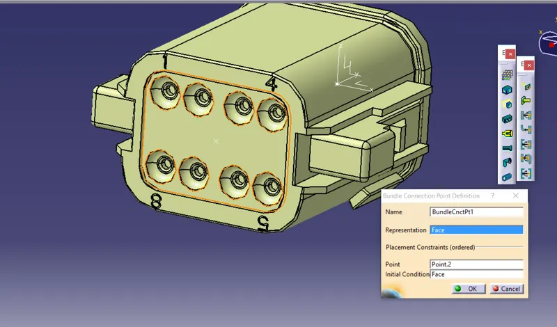
- Then Connector and bundle connection point should be given.
- All the publication were seen on the tree.
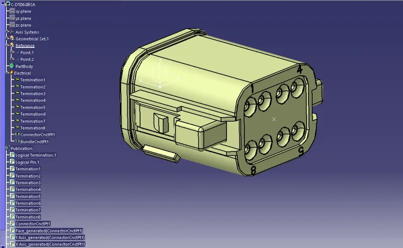
The parameters edited were point and axis which are shown below:
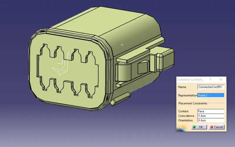
Connector definition and bundle, connector connection points were performed in electrical design workbench
MODEL 2:
- This is a female terminal which has both connector definition as well as a mounting slot by a clip.
- So in this model there should be a connection definition, connection, bundle point connections.
- Cavity definition and cavity connection points also must be given.
Parameters like point and axis is given in the below image:
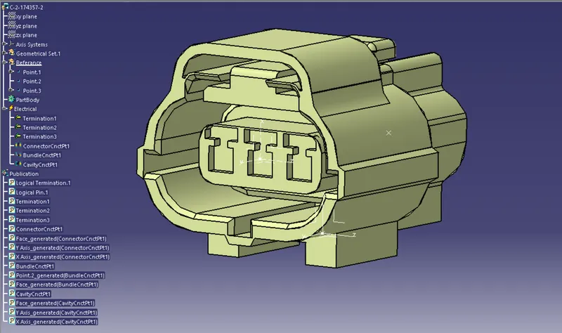
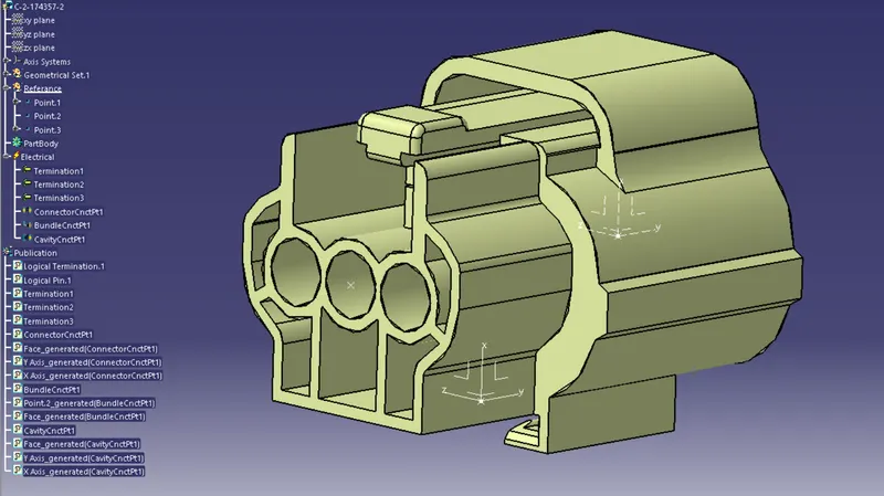
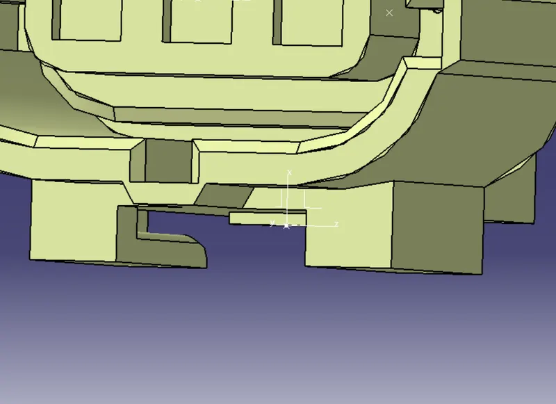
Now connector definition and connector, bundle , and cavity points should be given:
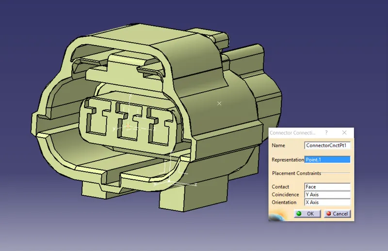
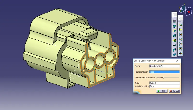
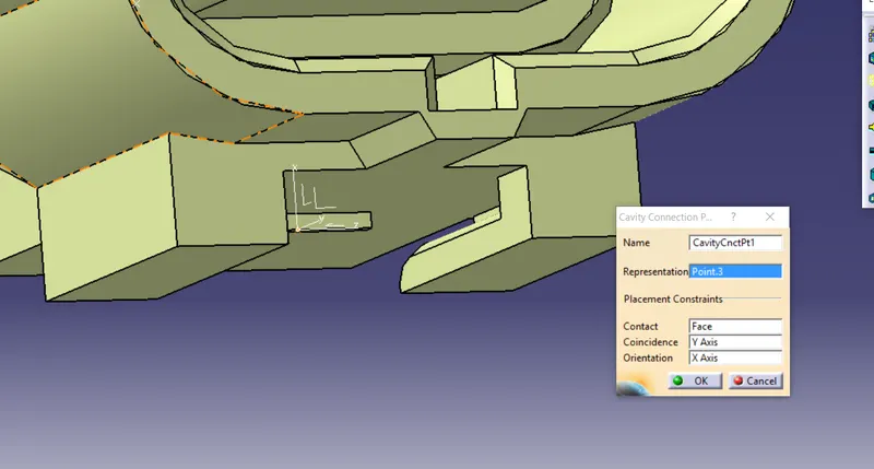
Now cavity and cavity connections point should be defined in the electrical design workbench which is shown in the below tree:
MODEL 3:
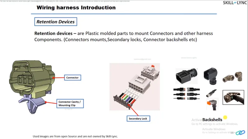
Mounting clips are retention devices which are used to mount the connectors to the vehicle body.
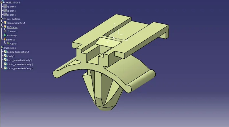
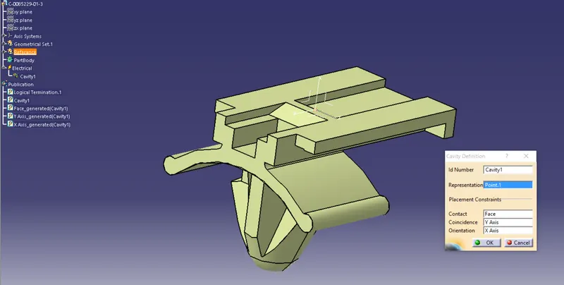
Now this device is defined as a mounting device and cavity device then cavity connection point is added by giving necessary parameters like point and axis.
This is a point for reference and also it is defined as a mounting device.
ELECTRICAL ASSEMBLY :
Now the Individual parts are added into the Electrical Assembly workbench inside a product and then assembled using connect devices.
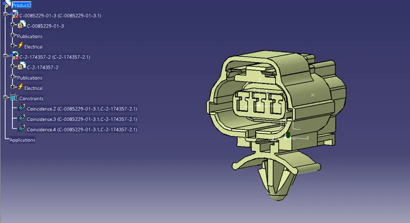
CATALOUGE For Components:
Now catalogue is created for easy changing or modification of product insted doing all the steps once again which saves the time.
Below is the catalogue window shown:
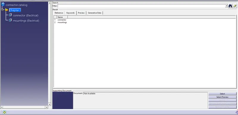
The new catalogue is created by using add family command and then it is saved in the desired location.
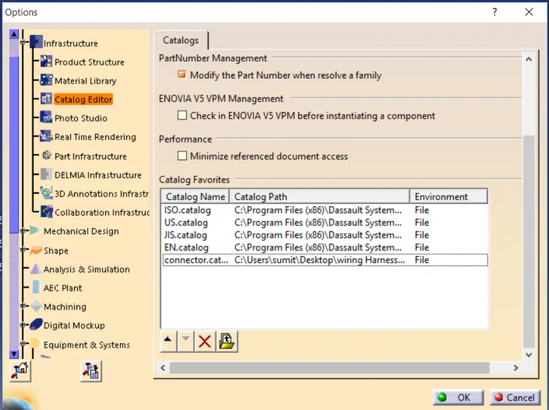
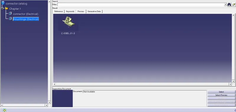
After saving the catalogue this catalogue is added in the catalogue editor as shown below:
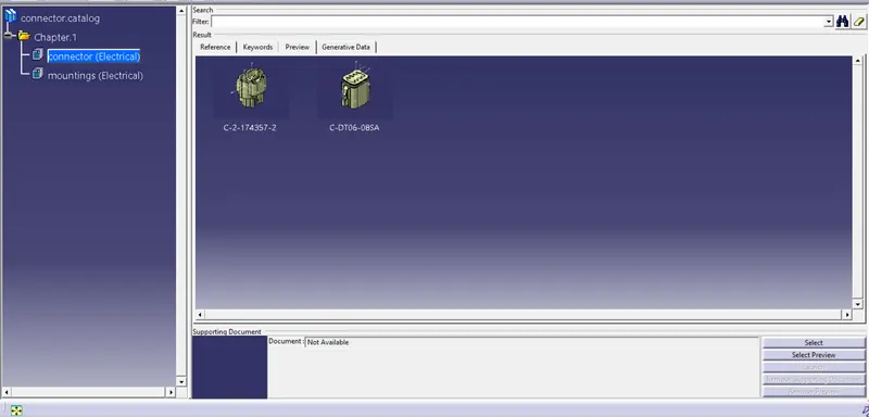
Here catalogue is saved in the name of connector which is shown below:
…