FINAL INDEPENDENT PROJECT
MODELLING OF HYUNDAI VENUE-SANJEET MARGHADE
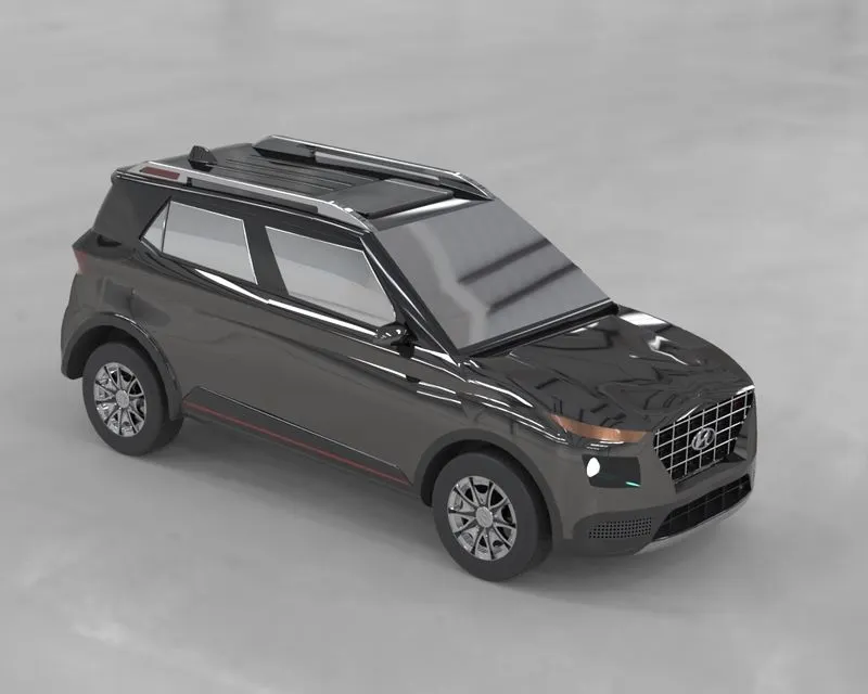
Title :
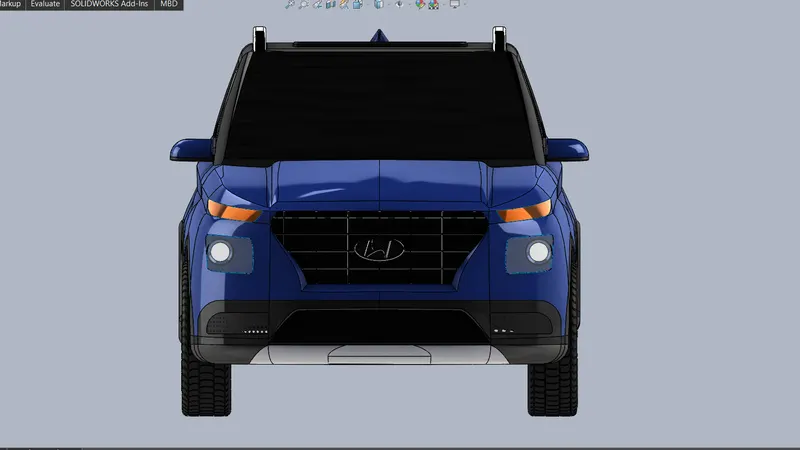
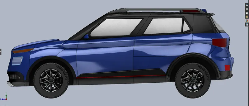
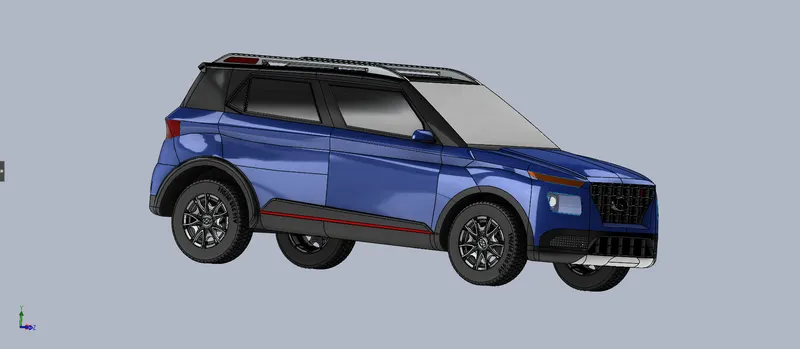
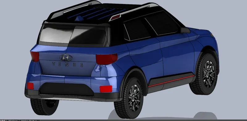
SOLID MODELLING, SURFACING AND RENDERING OF HYUNDAI VENUE CAR.
Objective :
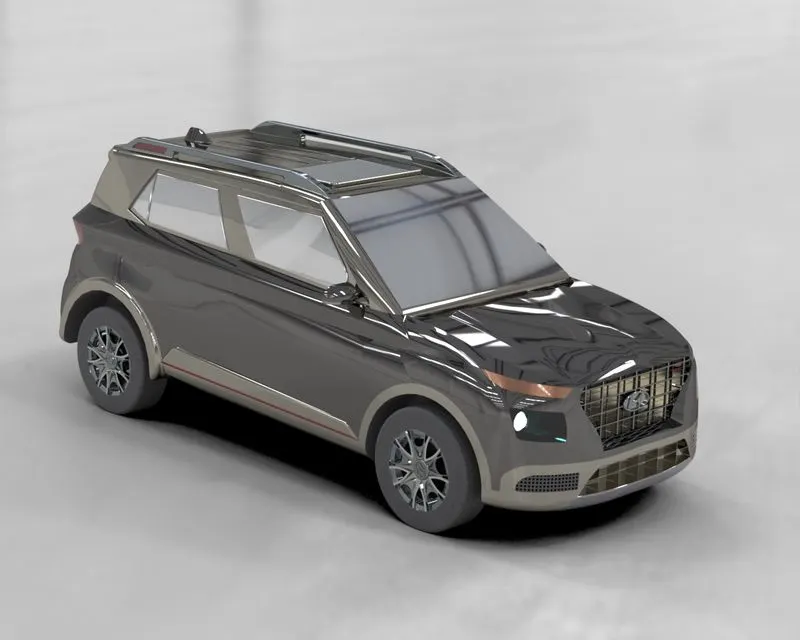
The main objective of this project to design and modelling of components of car, using sketch tools and 3D modelling features of Solidworks.Assembly of car using Solidworks assembly tool and Rendering images of car in Photoview360 and Solidworks visualization with different environments and views.
Introduction :
The Hyundai Venue is a subcompact crossover SUV manufactured by the South Korean manufacturer Hyundai. Derived from the platform of the Accent it was Hyundai's smallest crossover globally prior to the introduction of the Casper. The Venue debuted at the 2019 New York International Auto Show. In this project we are going to use SOLIDWORKS software to model car and render photo realistic images using SOLIDWORKS visualization.
Hyundai Venue specifications :-
Designer –Chan-Hee Lee, Duck-Hyun Hwang and Goo Lee
Body style – 5 door suv
Layout – Front engine, front wheel drive
Engine displacement – 1395cc(Petrol) and 1968cc(diesel)
Transmission –6 speed manual
Max. Torque – 115Nm(Petrol) and 240Nm(diesel)
Mileage – 17Kmpl(Petrol) and 23Kmpl(diesel)
Length : 3995 mm
Width : 1770 mm
Height : 11565 mm
Wheelbase : 2520 mm
Tires size : 195/65 R15 91V
Description:
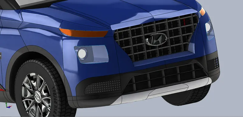
The designing software allows the engineers to create the virtual models before a product is produced, and it also allows for much better visual representation of the product before manufacturing. It also helps engineers with various analysis to know whether product is ready for manufacturing or not. SolidWorks is a 3D CAD design software, analysis software and product data management software developed by Dassault systems. This software enables the designers and research engineers to model the products better, faster and more cost-effective. In this project we used solid modelling features to model part of car and used surface modelling features to give shape to vehicle body and later we converted into solid body to give some extrudes and cuts. Journey starts with blueprint setup and ends with rendering.
Modelling Procedure :
WHEEL :
1. Start with a sketch at 406.4mm diameter, in front plane. revolve it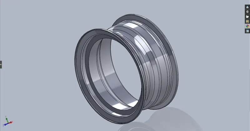
2. Now draw some circle with arc in plane selected. Use this drawing to apply revolve feature by changing angle to 72' instead of 360 which results in some sector of circle shapes on the rim.
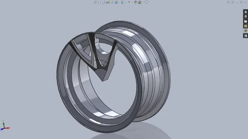
3. Draw some sketchehs on the sector extrude it than make dome on it make slot chamfer it
4. Use circular pattern feature, to distribute slot on face equally, with number of instances 5.
5. Apply dome on circular slot and pattern it with 5 instances.
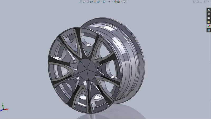
6. Make logo on centre of ring and extrude it 3mm.
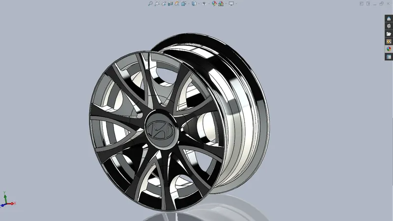
7. circular component mounted on rim. This is tire.Draw a rectangle with arc in right plane and use cut revolve to smoothen edge of tire.
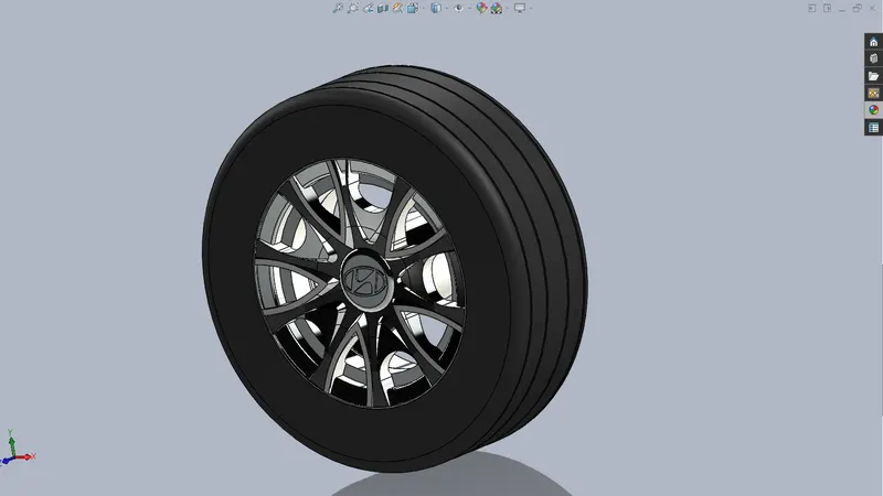
8. Make tread pattern on tire and cut extrude it. Distribute tread pattern on tire with circular pattern feature.
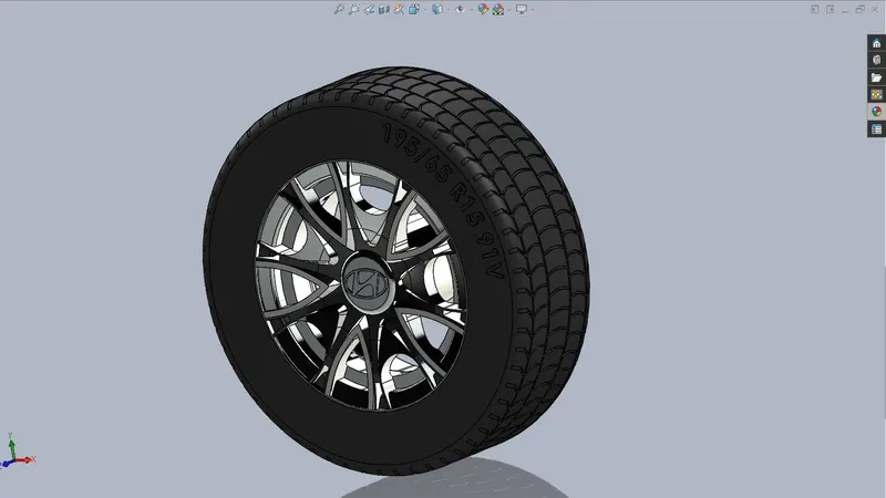
9. Apply appearance and save the file.
Design of the body of Hyundi venue
Blueprint set up And Designing :
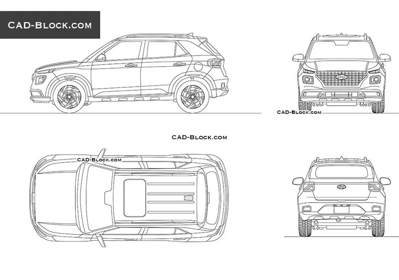
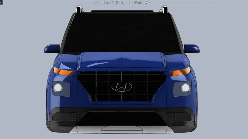
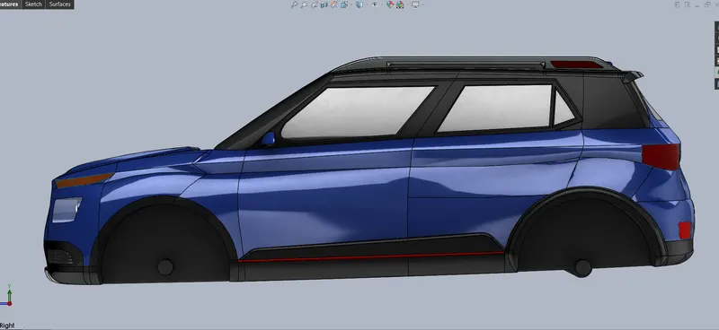
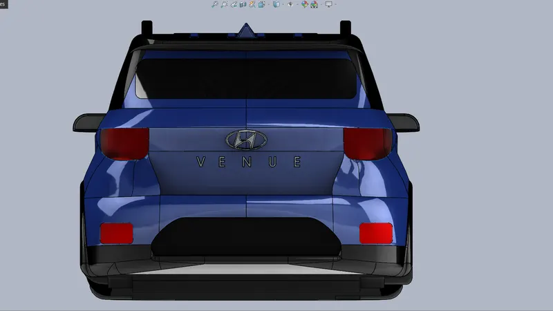
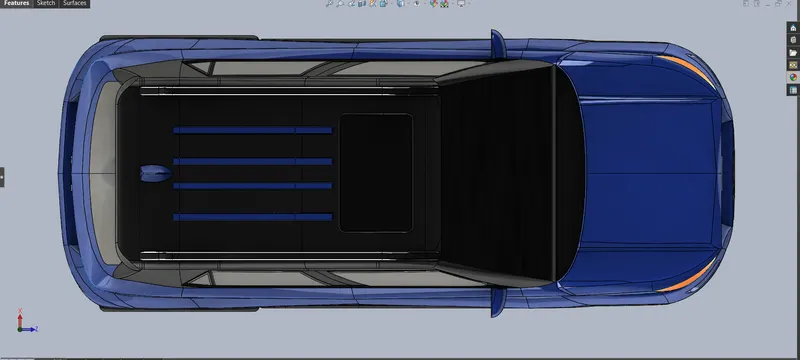
The blueprint is first edited using photoshop and cropped to each view, and image size is changes as per the standard dimensions.The blueprints image of the car are set as reference in accordance with original vehicle dimensions to help create curves and boundaries of the vehicle surface.various mates such as coincidence, concentric, width, etc.
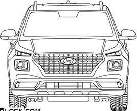
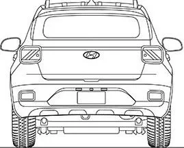
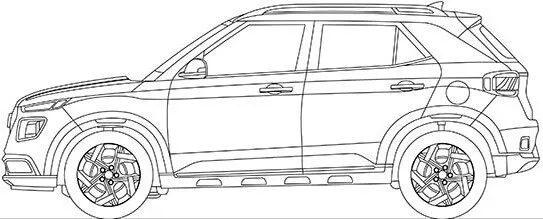
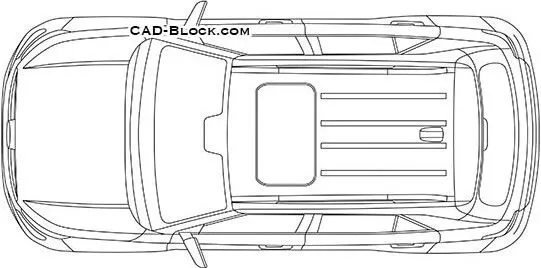
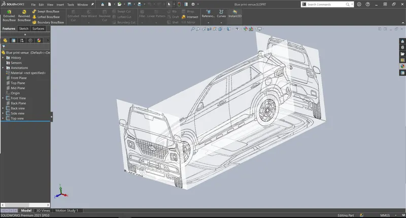
The main body of the car is created using the surfacing tools. Different curves are generated using the projecting the sketches which are drawn in reference to the blueprint.
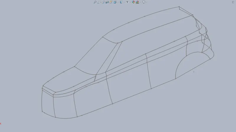
Most commonly surface loft, filled surface and trim surface tools are used.
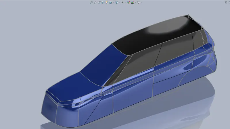
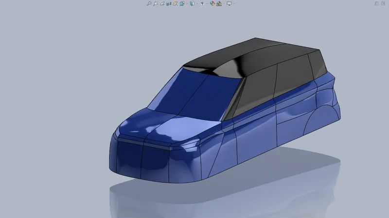
The main features used to create the main body are curve projection, surface loft, filled surface, extrude surface,
sweep surface, trim surface, mirror surface, knit surface, etc.
Assembly
There are two types of approaches in assembly of a model. Top down and bottom up approach.
Top-down Design:
In Top-down design, parts' shapes, sizes, and locations can be designed in the assembly. For example:
You can model a motor bracket so it is always the correct size to hold a motor, even if you move the motor. SOLIDWORKS automatically resizes the motor bracket. This capability is particularly helpful for parts like brackets, fixtures, and housings, whose purpose is largely to hold other parts in their correct positions. You can also use top-down design on certain features (such as locating pins) of otherwise bottom-up parts.
The design of photocopier can be laid out in a layout sketch, whose elements represent the pulleys, drums, belts, and other components of the photocopier. You create the 3D components based on this sketch. As you move or resize elements in the sketch, SOLIDWORKS automatically moves or resizes the 3D components in the assembly. The speed and flexibility of the sketch allows you to try several versions of the design before building any 3D geometry, and to make many types of changes in one central location.The advantage of top-down design is that much less rework is needed when design changes occur. The parts know how to update themselves based on the way you created them.You can use top-down design techniques on certain features of a part, complete parts, or entire assemblies. In practice, designers typically use top-down techniques to lay out their assemblies and to capture key aspects of custom parts specific to theirassemblies.
Bottom-up Design:
Bottom-up design is the traditional method. You first design and model parts, then insert them into an assembly and use mates to position the parts. To change the parts, you must edit them individually. These changes are then seen in the assembly.Bottom-up design is the preferred technique for previously constructed, off-the-shelf parts, or standard components like hardware, pulleys, motors, etc. These parts do not change their shape and size based on your design unless you choose a differentcomponent.
Rendering:
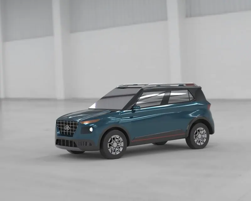
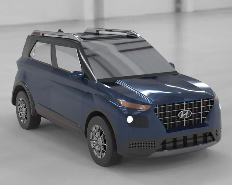
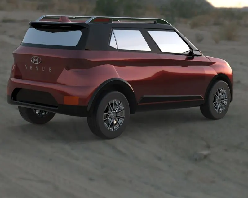
The photo realistic renders are created in SolidWorks using the add-in called PhotoView 360. The rendering of the image include setting up the environment, arranging the lights, setting up the scenes and creating the final view of the designed part. SolidWorks visualize is also an add-in which is used to create the high quality rendered images with minimum amount of time.
Conclusion
The project gave me a good understanding of how to convert a 2D blueprint into a nice 3D model. The surfacing and solid modelling are completely done in SolidWorks 2019. I got a good understanding of the surfacing modelling and learned about how to create the complex curves using project curves tools. In assembly, I learned about using the advanced and mechanical mates. Applying different background scenes, lights and setting up cameras in PhotoView 360 to create a good rendered views.
Reference:
https://www.cardekho.com/hyundai-venue-360-view.htm#leadForm
https://cad-block.com/1167-hyundai-venue.html
https://en.wikipedia.org/wiki/Hyundai_Venue
https://www.youtube.com/watch?v=ckzkIMpglYU&ab_channel=CendingenieriaS.A