Week 9 - Project 1 - Door Trim Lower with Engineering Features
DOOR TRIM LOWER WITH ENGINEERING FEATURES (HEAT STAKES AND LOCATORS)
Aim: To design a solid body from the given class A surfaces by creating tooling axis, B and C surface then do the draft analysis for the same then conclude the result by adding engineering features like heat stakes and the locators.
Objectives:
• Creation of Tooling axis with appropriate draft angle.
• Creation of other surfaces (eg, B and C surfaces) for creating a solid component. • Perform Draft analysis on Class A surface and Solid model hence created.
Tooling Axis creation:
It is defined as the direction in which the mould/core and cavity open. Selection of the direction of the tooling axis depends on the ease at which components can be easily ejected.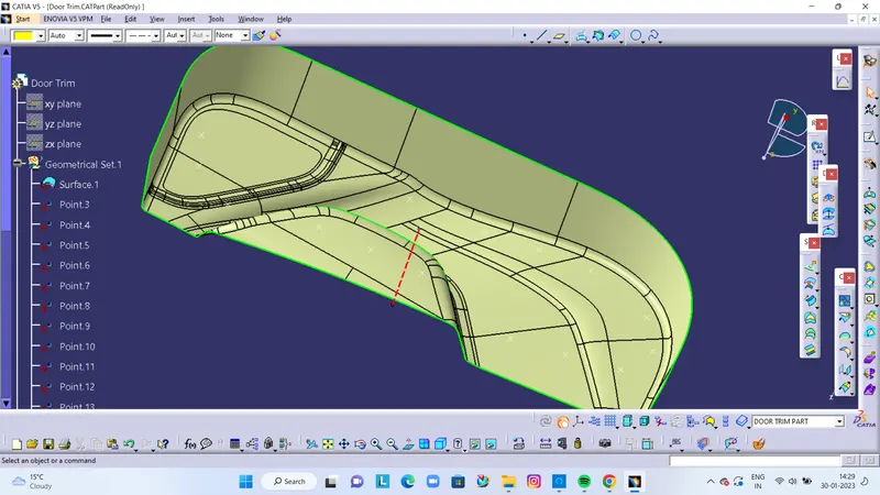
CREATING B SURFACE
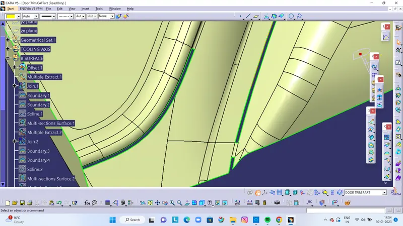
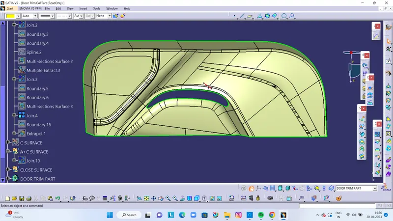
To create the class B surface, offset the class A surface inside as per our thickness requirement (here the thickness is 2.5mm, so I offset the class A to 2.5mm inside). Once the offset is created, we can observe some patches on the offset surface by taking the boundary for the offset surface, those patches are formed due to the fillets on the class A surface. We need to cover those patches with the help of the multi-section surfaces command by extracting the patch boundaries. Once all the patches on the offset are covered properly join all the patches with the offset surface, to get the replicated surface of the class A surface.
FINAL B SURFACE
CLASS C SURFACE:
I used the sweep command to create the class C surface concerning the boundary of the class A surface. Initially, I extracted the boundary of the class A surface with tangent continuity, and I sweep the extracted boundary concerning the surface.Once we sweep all the surface boundaries of class A, extrapolate the sweeped surfaces until both surfaces got intersect properly, and trim them to remove extended extrapolated surfaces to get a proper sweep boundary throughout the entire surface, including the centre hole of the door trim. Now, join both class A and sweep boundary to get the complete class C surface.
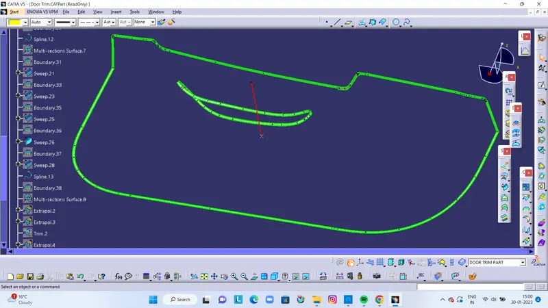
JOIN A+C SURFACE
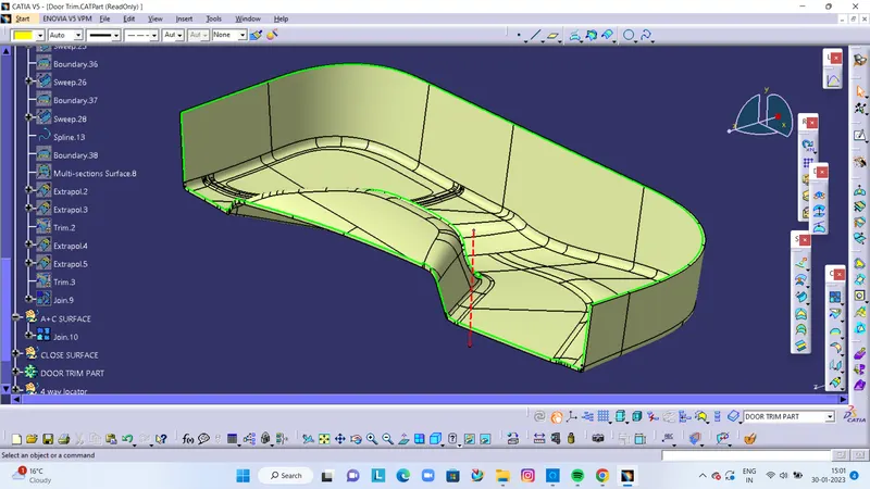
CLOSE VOLUME
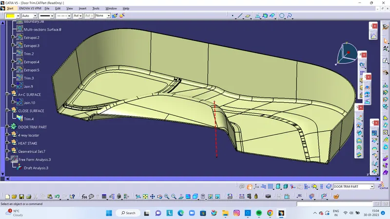
PART BODY
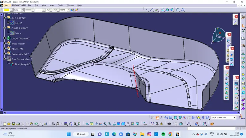
CREATION OF LOCATORS:
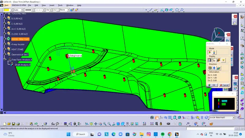
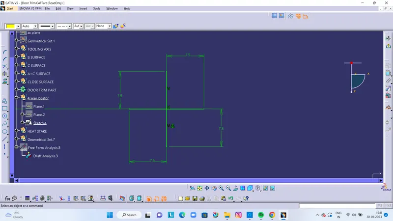
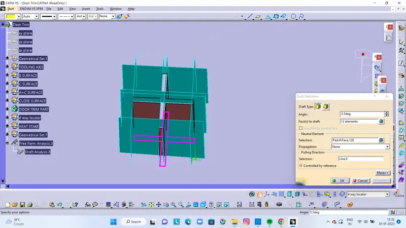
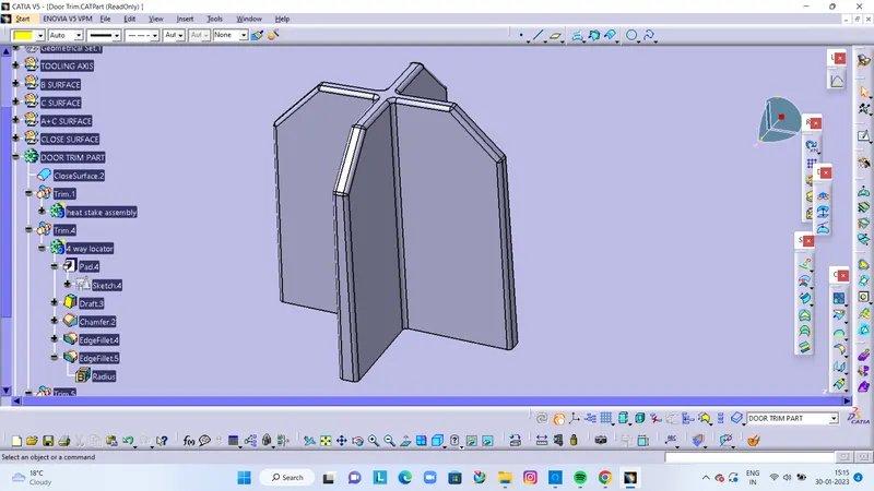
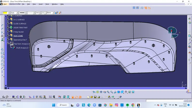
To create the locators, I created a sketch on the body. After creating the sketch, I pad it thicken it to 1.3mm and I drafted it with 0.5deg in the direction of the tooling axis. I gave 3mm of chamfer with 45deg of inclination and after I gave a fillet of 0.25mm radius.
CREATION OF HEAT STAKES:
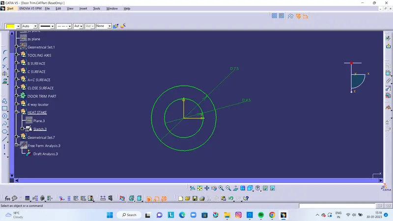
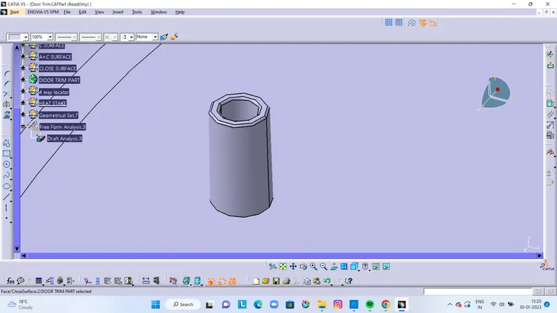
To create the heat stakes, I draw a sketch on the surface. After the creation of the sketch, I pad it to 12.5mm height and I gave a draft angle of 0.5deg on both sides (inside and outside) and then I gave a fillet with a 0.25mm radius.
TRANSLATE HEAT STAKE BY POINT TO POINT
DOOR TRIM WITH HEAT STAKE & LOCATOR
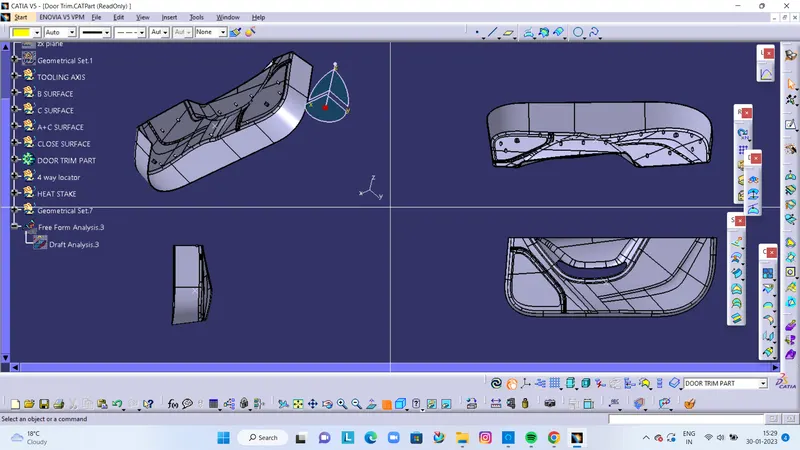
DRAFT ANALYSIS