Week 9 - Project 1 - Door Trim Lower with Engineering Features
Aim: Making 4-way locators and Heat Stakes on a CATIA Component and draft analysis of the final body.
Theory: -
Draft angle: A draft angle is a slant that is applied to each side of most features of an injection moulded part. The angle, which is positioned to run toward the direction of a mold's pull and parting line, helps with releasing the part from the mold.
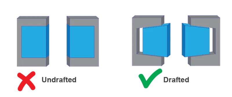
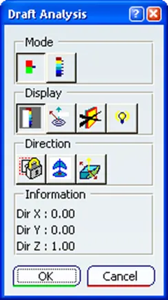
Draft analysis: The Draft Analysis allows the user to easily analyze a part for a proper draft angle. A Draft Angle describes the amount of taper for molded or cast parts perpendicular to the parting line. Find the Draft Analysis in the Tools tab. Draft Analysis is applicable for 3D part models.
Heat Stakes: Heat staking also known as thermoplastic staking is the process of joining two dissimilar materials together. In heat staking, we use local heating and cooling to raise the temperature of plastic components and allow plastic reforming to be carried out. This reform can be used in a wide variety of applications.
>Heat staking can be performed using a wide range of thermoplastic materials including polypropylene, ABS, polycarbonate, and many others. The integrity of a thermal staked assembly depends greatly upon the geometric relationship between the boss and the thermal tip.
4-way Locators: These are the fixtures used to constrict the movement of the desired part in 2 axes in both positive and negative directions.
Tool Axis Creation: -
In Molding, machine arrangement is given to open the mold along a direction which is known as Tooling Direction.
1. Likewise in our model, we first create a tooling axis from a flat surface. Here we first orient the model in the Y direction and extract a flat surface. Then we take a point the body center and draw a line in Y direction.
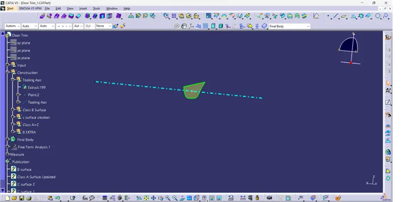
2. Note: To create a tooling axis using one of the 2 mostly used methods, i.e
> From a large circular contour
> From a large flat surface.
3. Now we move on to make the B Surface:-
As there are different components in the body, hence it is recommended that one should segregate and split the parts for easy surface generation and also cascade the components in orderly manner.
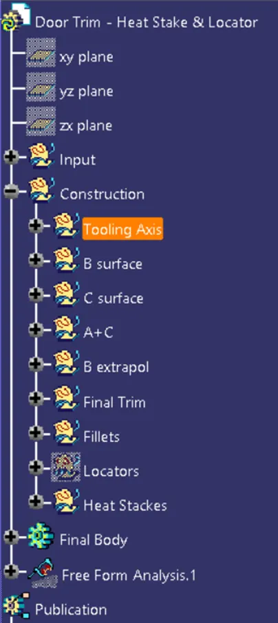
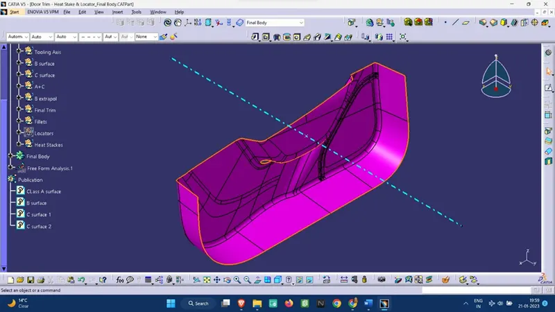
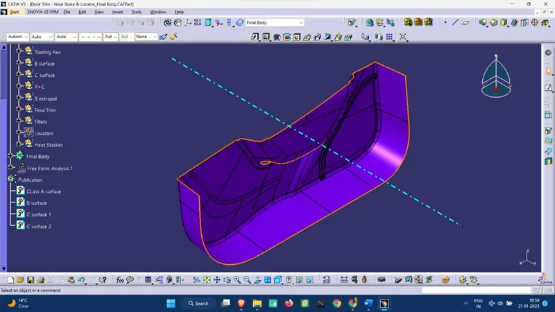
> For Surface Generation we first offset the Class A Surface and then we use the ‘Join’ and ‘Sub-element to remove’ commands to fill any holes and gaps as from offsetting a large surface, some of the fillets may not be generated.
> Now we measure the fillet from the Class A surface and as surface B is inside the Class A surface, hence we will add the thickness value along with the fillet value.
Note: For areas that are too intricate, then we may give the exact value of the fillet or give a nominal value to the fillets for smooth surface generation.
> Now we move to make the C surface, where we first make a boundary at the edge and use the ‘Sweep command’ for surface generation.
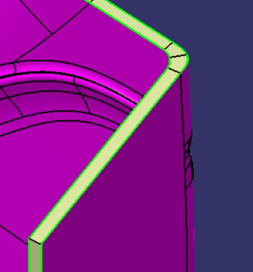
Note: One should always remind that B Surface should not be generated above the Class A surface as the Class A surface holds the aesthetic value and comes in direct contact with the consumer, therefore no changes should be made to the class A surface.
Design of the 4 way Locators:-
> We need to first have a plane and a point for the positioned sketch of the 4-way locator.
> Now we sketch a cross of about 15 mm keeping the point as the midpoint.
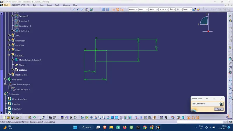
> Then we extrude them with a thick profile.
Note: The height of the Locators should be nearly equal throughout.
>Then we add a chamfer of (1mm with 45 deg) and fillets
> Now we add a 0.5 mm draft to the locators.
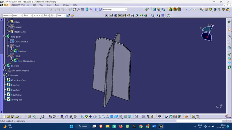
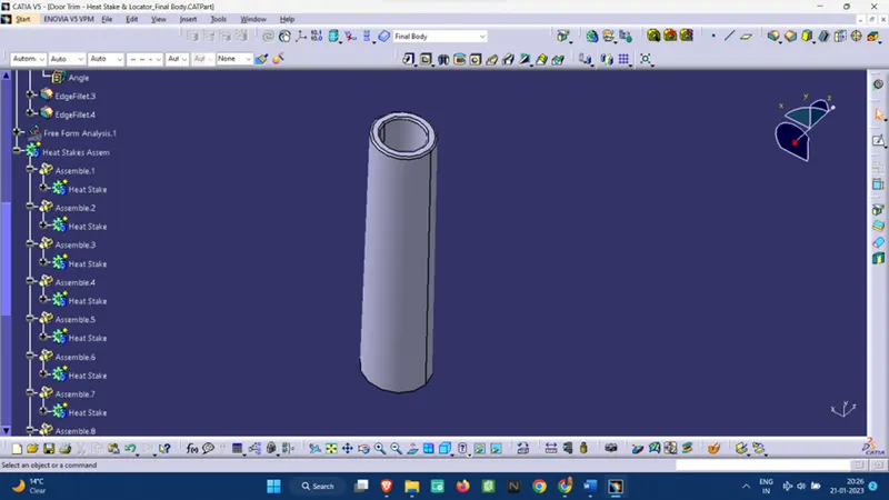
Design of the Heat Stakes:-
> We first sketch two concentric circles (Dia depends on the manufacturer) using the positioned sketch.
> Now we extrude them.
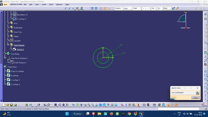
Note: The height of the Heat Stakes should be less than the height of the locator as the locators are used first and then the temperature difference is created for the heat stakes.
Multiple Profile:-
For both Heat Stakes and 4-way locators, after designing 1 component, we do the following steps to create multiple profiles:-
> We copy the entire part
> Then paste it in the main body using the “Paste Special à with link” command.
> Now we have a copy of the original part after which we translate the part using point-to-point translation.
>Then we union trim the excess par with the main body.
Draft analysis: -
Standard Measurements:
Model Thickness: 2.5 mm
The minimum Draft angle provided: 3 deg angle
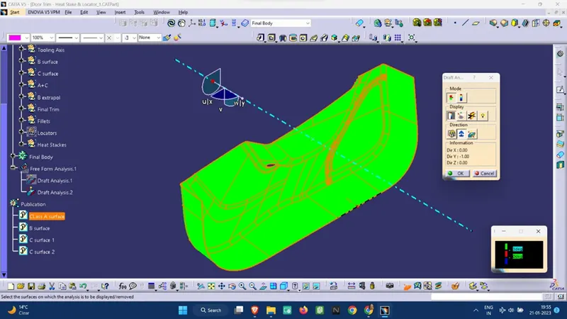
Class A surface Draft analysis:-
Final Body draft analysis: -
1. Final Body without Attachments.
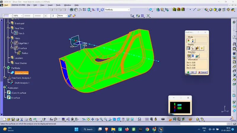
2. Final Body with Attachments:-
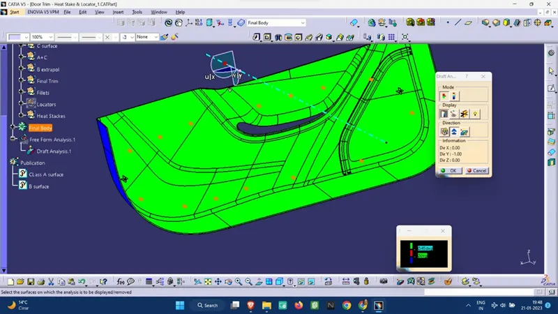
A different view of the draft analysis:-
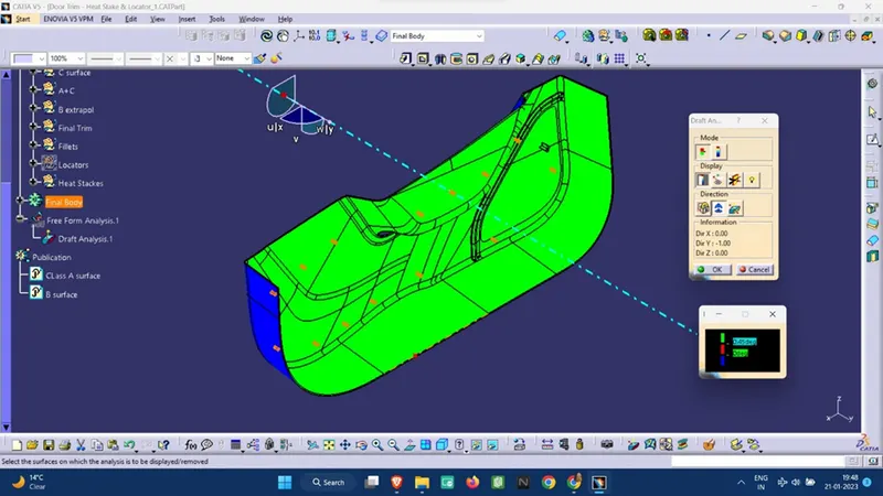
Isometric View: -
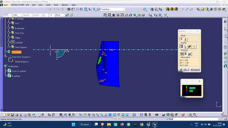
Front view: -
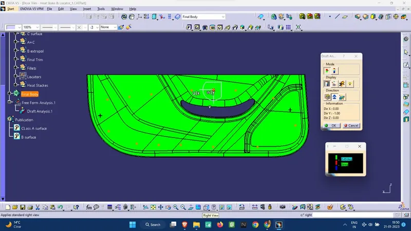
Side View:-
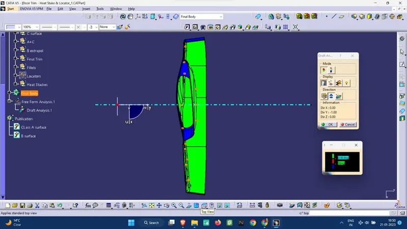
Top View:-
Note:
Green Surface: Denotes that the model satisfies the required draft angle
Blue Surface: Denotes that the model draft angle is below the required draft angle.
Different surfaces:-
Class A surface:
Class B surface:
Class C surface:
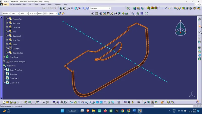
Note: To generate the Class C Surface, we have used “Sweep Command” along with the “Reference to surface” option at 93 degrees (3 Deg as Draft angle), as in this part the C surface is at a right angle with the Draft axis.
Conclusion: Draft analysis is a very essential tool for manufacturing a plastic product using Core and cavity manufacturing techniques, hence draft angle should always be provided appropriately.
>>Applications of Heat Stakes range from staking plastic bosses for the assembly of car door panels to joining PCBs to plastic housings. Benefits of this technique include; no vibration damage, no particulates, the ability to stake metalized coated applications, and the capability to stake in difficult-to-access or restricted areas.