Week 9 - Project 1 - Door Trim Lower with Engineering Features
DOOR TRIM LOWER
Aim: To Create the Door trim lower component through the given Class-A surface.
Objectives:
• Creation of Tooling axis with appropriate draft angle.
• Creation of other surfaces (eg, B and C surfaces) for creating a solid component. • Perform Draft analysis on Class A surface and Solid model hence created.
DRAFT:
THE Draft is the amount taper of moulded parts perpendicular to the parting line. draft angle ar given to component to easy release from the mould. it will reduce the risk of damage and ensure that it can be ejected from the parts, with out draft will endure the wear and tear which will reduce the tool life and you may not able to enject the component from the mold. Also important to overcome the vaccum forces by letting the air inbetween the metal and the plastic to release properly.draft also ensure the smooth finish also cutting down the cost by reducing the cooling time.
Procedure for creation of Solid model:
CLASS A SURFACE
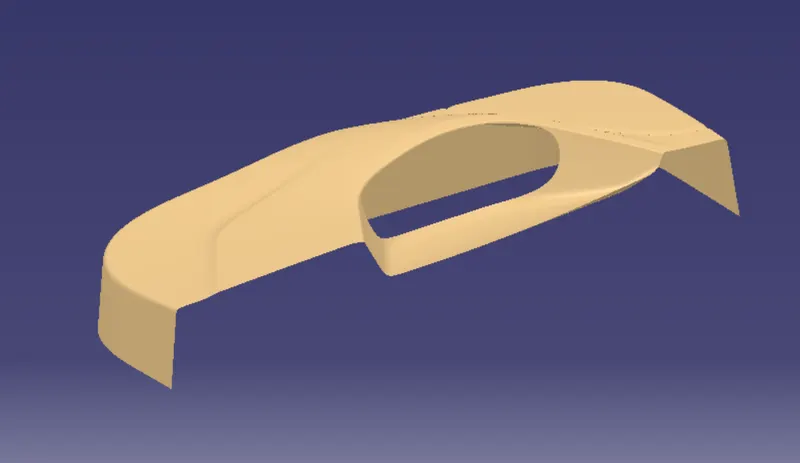
TOOLING AXIS CREATION;
It is defined as the direction in which the mould/core and cavity open. Selection of the direction of the tooling axis depends on the ease at which components can be easily ejected.
Creation of the tooling axis By analysing the component the most easily ejectable direction is somewhere close to the Z direction
Extract surface from the flat A surface
using the extracted A surface insert the point , and introduce line in z diection and which clears the A surface
CLASS A SURFACE TOOLING AXIS
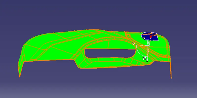
Draft Analysis of Solid Model
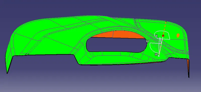
the nomial draft angle for the plastic components is 3 degrees. for the 2.9 degree is given as the degree for draft analysis for the component . the draft analysis colour scale window in where green bar show the draft angle ablove 2.9 degrees and whereelse the blue bar show angle below the 2.9 degree . other limit being and the orange bar shows the negative draft angle. As shown in the image below all the top faces and side faces of the component are green, while the bottom faces are orange .The solid model has cleared the draft analysis successfully as shown in the image below.
B-SIDE FEATURES
RIBS:
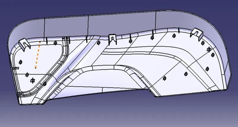
Ribs are the feature of the plastic injection parts. there are thin extension which run perpendicular to the wall which support the wall.Thickness and location are essential to rib design.First, the base surface where the rib has to be created is extracted using the Extract command
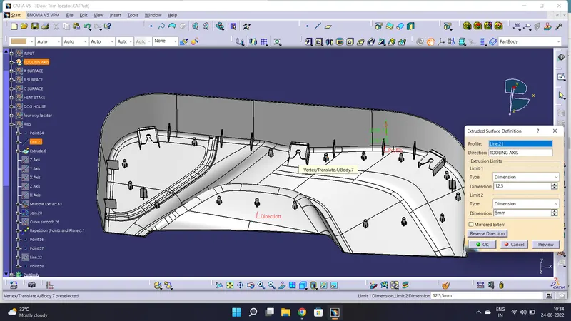
Next, the profile is extruded, to find the height,h=Wall thickness * 5
=2.5*5
= 12.5 mm
Therefore, the height is 12.5 mm
The extruded surface is thickened,
Thickness,w=0.4*t
=0.4 2.5
=1mm
Therefore, the thickness of the rib is 1 mm,The draft is applied to the sides of the ribs. As per the design rule, the ideal draft angle is 0.5 deg
Rib root thickness
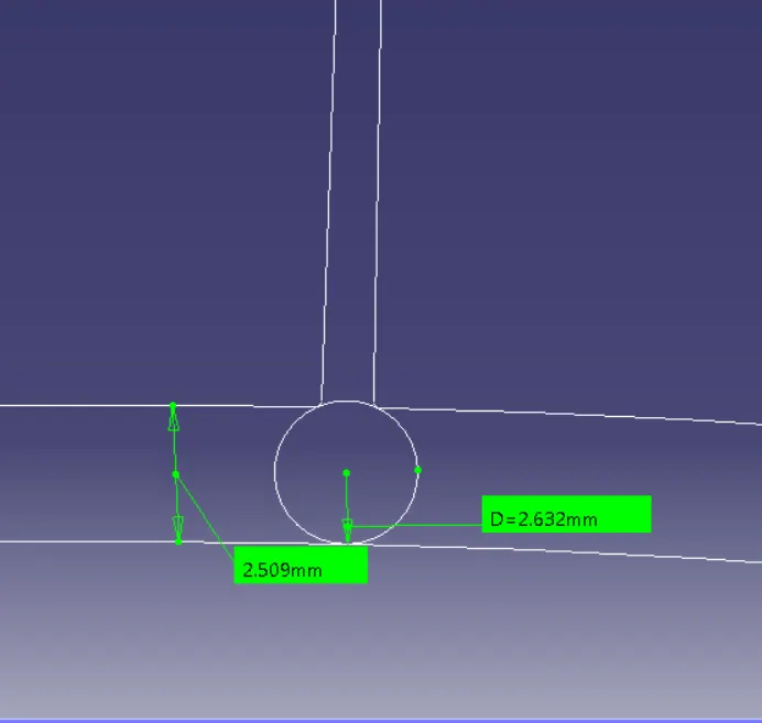
To check for the Rib root thickness, We have to take an Intersection with the XY plane and the Coin holder component. Once we get to the intersection we have to create a tri-tangent circle at the rib area and measure it. The value must be within 30% greater of the
Heat stakes
The locators restrict all the degrees of freedom expect in the translation in the y direction of tooling axis. for restricting we are using the heat stakes , the draft are applied to the ribs as per the design rule ,the ideal draft as per the design rule the draft angle 0.5 deg andThe draft is applied to the sides of the ribs and fillet can be 0.25cm,Hence, the ribs are created for the screw HEAT STAKES
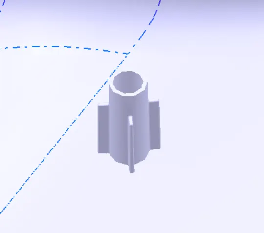
LOCATORS
Locators and heat stakes are used to fix with other components, locators and heat stakes are used to restrict all 12 degress of freedom so it is used. the locators also follow rib design rules and will be given a minimum draft of 0.5 degrees and a minimum fillet of 0.2mm and an entry chamfer of 3mm. This entry chamfer is given so that the locators can mate with the other part easily.The draft is applied to the sides of the ribs. As per the design rule, the ideal draft angle is 0.5 deg
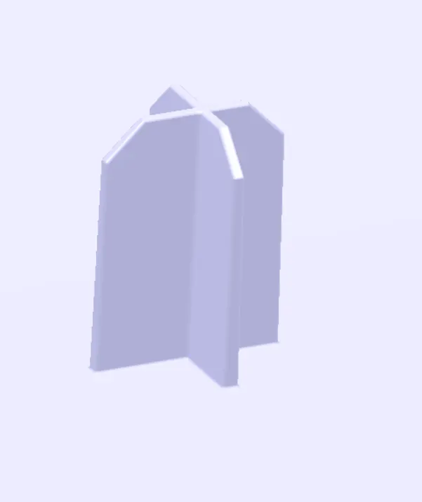
DOGHOUSE
the doghouse is a engineering feature used in plastic design,dog houses are the supporting features.Sometimes other engineering features like snaps; locators, etc. are mounded on them to increase their strength.
the doghouse is created by following the design rules:
the nominal wall thickness guide range 0.75m to 3mm for reinforced materials and and 0.5 mm to 5 mm for unreinforced materials
the height of the doghouse maintian has per design rules 30mm and and thickness as per design rules and hog house wall thickness at the intersection of part wall should be 40 percent of the main wall thickness and the height of intersection are should be maintained between 3 to 6mm height
WALL THICKNESS (W) = 0.70 (NOMINAL THICKNESS OF PLASTIC MATERIAL)
This process is usually done by Thicken surface command.The fillets and the draft are given as per the design rules.
An important thing while designing a doghouse is to maintain 40% less thickness than the wall thickness (T) at the area of the intersection to avoid sink marks. So, a C shape is formed at the intersection.
This can be made using the split command to remove the solid at the intersection

Draft Analysis
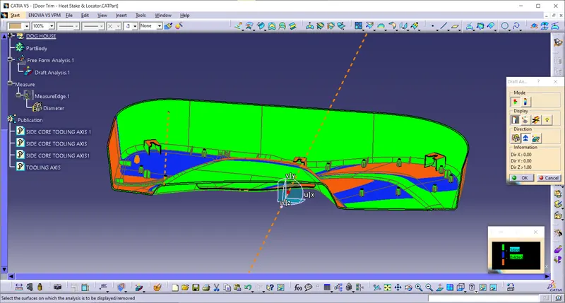
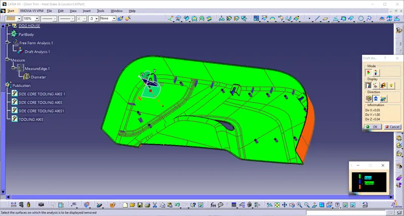
views
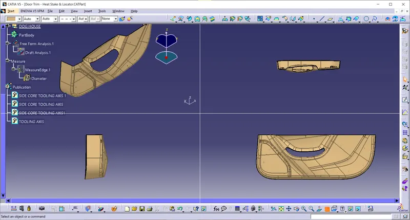
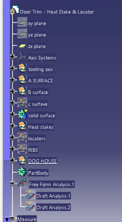
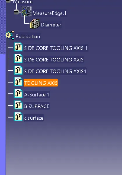
tree structure