Week 8 - Challenge 3 - Switch Bezel Design
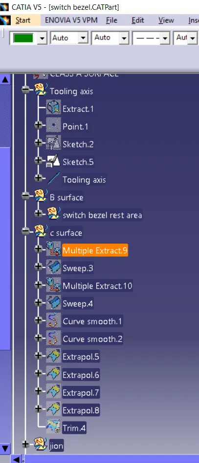
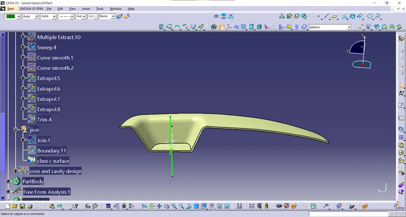
Tooling axis :
- Extract the base surface of the switch bezel and create a point on it using the surface option
- insert axis system in the point. create a sketch using yz plane
- use the intersection on it. and draw the line on the both instersection
- By using bisecting line option create a one-line the tooling axis y direction
- By using the same method create a sketch xz plane and make an intersection on it make interaction and draw a line and draw another line with 5 to 6 degrees from the first line which tooling axis of x-axis
- use the bisecting option in both sketch lines and create main tooling axis
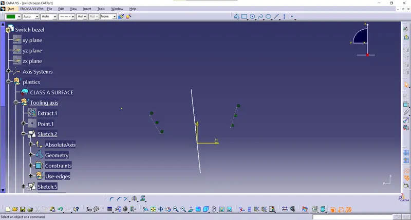
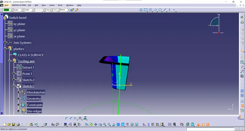
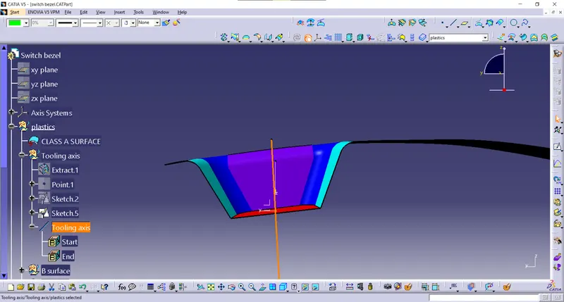
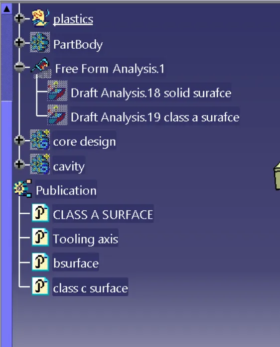
draft analysis
- nominal draft angle is 3 deg and for subassembly is 7 degree
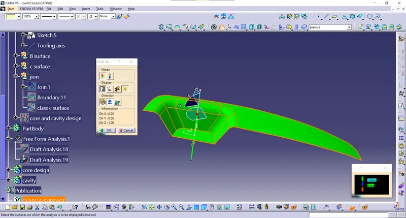
- using feature draft analysis option
- At the first position, the compass on the tooling axis of the component then lock the compass and click on the component where x appears of that color of the component changes
- the color indicates the various conditions of the draft angle and green where parts are accepted and further processed
- by using analysis on the running point icon various surface position is seen
- 3 deg which satisfies the surface which can be seen in green color
- '
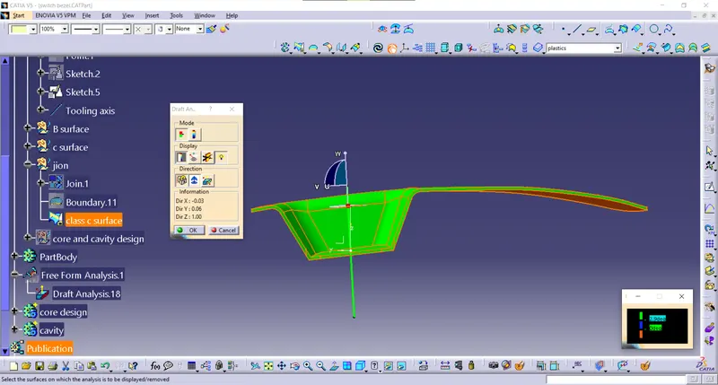
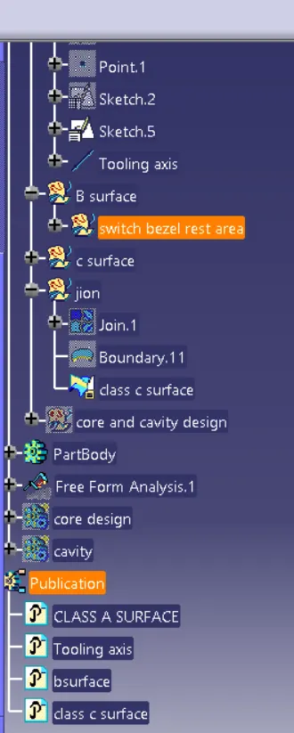
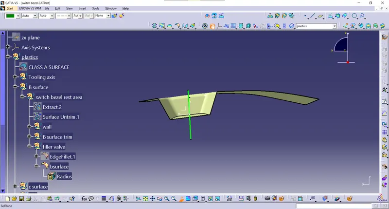
class b surface
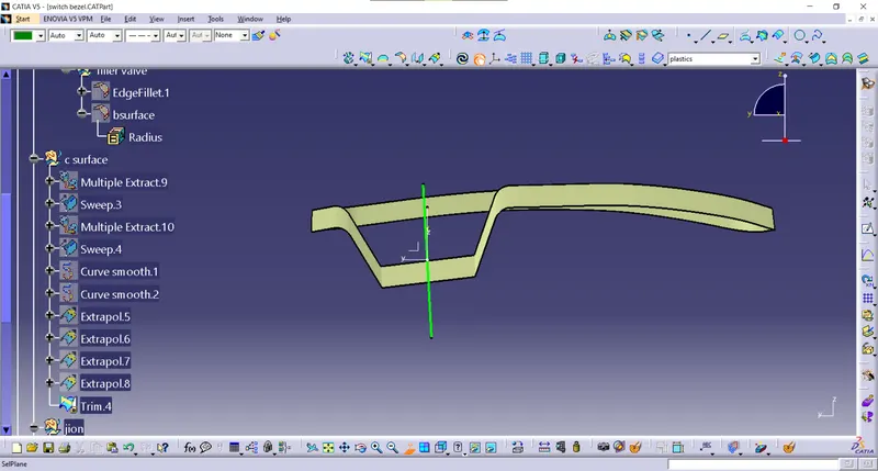
class c surface
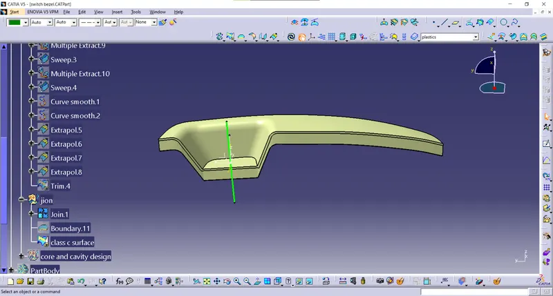
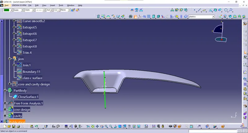
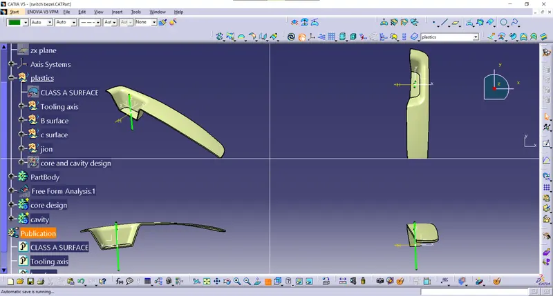
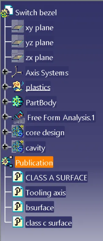
TREE STRUCTURE