Week 9 - Project 1 - Door Applique Design with Engineering Features
Aim: To design a Door applique with Engineering features like Heat stach, Locators given with stylish aurface/class A surface and draft analysis for Manufacturing process.
Theory:
HEAT STACK
Heat staking also known as thermoplastic staking is the process of joining two dissimilar materials together. In heat staking we use local heating and cooling to raise the temperature of plastic components and allow plastic reforming to be carried out.
MATERIAL FOR HEAT STACK
Heat staking technology is ideal for most native and blended thermoplastics on the market today, as well as the most robust glass and/or other-filled plastics. It produces high quality results when used with any of the following materials:
Polycarbonate (PC)
Polypropylene (PP)
Polystyrene (PS)
Acrylonitrile butadiene styrene (ABS)
Nylons (GFN or Nylon6/6)
Ultem (GFN or Nylon6/6)
BENIFITS FROM HEAT STACK
Similar and dissimilar materials may be joined: metal to metal, plastic to plastic, metal to plastic
Accurate control operating within a small process window
Local heating resulting in no damage to surrounding materials
Processing of glass-filled materials
No mechanical vibration
Many heat-stake shapes possible through custom designed tools
WORKING PROCESS FOR HEAT STACK
When an electrical current flows through the heating tip, the electrical resistance creates heating effect. The heat staking tip is brought into contact with the thermoplastic part to be reformed.The heating tip is then heated by direct electrical heating within the tip for a short period of time. The heated tip softens the plastic material and forms the melted plastic into the shape of the tip.
LOCATORS
3-2-1 PRINCIPLE
The 3-2-1 principle states that the six locators are sufficient to restrict the required degree of freedom of any workpiece. In this, motion is restricted using clamps and locators. A three-pin base can restrict five motions and six pins restrict nine motions
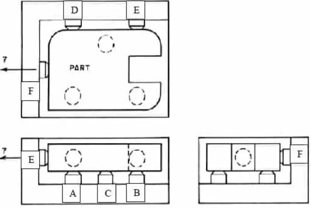
3-2-1 Principle consists of 12 degree of freedom
The Locating Process: Degrees of Freedom
In order to completely specify the position in space of a three-dimensional
object (such as the cube that’s shown), we refer to six coordinates:
Translational position along the X-axis
Translational position along the Y-axis
Translational position along the Z-axis
Rotational position about the X-axis
Rotational position about the Y-axis
Rotational position about the Z-axis
These six coordinates are known as the six degrees of freedom of a three-dimensional object. As the double-headed arrows indicate, the translational and rotational positions can vary in either direction with respect to each of the three axes.
We have two objectives when mounting a part in a fixture for machining:
1. Accurately position the part at the desired coordinates.
2. Restrict all six degrees of freedom so that the part cannot move
FIRST PLANE: Geometry tells us that three points are required to define a plane. This is the "3" in 3-2-1. So, three specific points are used to define the first plane.
- Use the largest surface of the part for the first ("primary") reference plane.
- Position the three support points as far apart as possible.
- If more than three support points are required to prevent deflection, make the additional points adjustable.
SECOND PLANE
A second plane, if it is perpendicular to the first, can be defined by two points, the "2" in 3-2-1. The part is now constrained to one degree of freedom: movement along the Y axis. (The part cannot move along the X or Z axes because it is held against the planes by clamping force.)
THIRD PLANE
A third plane, if it is perpendicular to both of the first two planes, can be defined by one point, the "1" in 3-2-1. The part is now entirely constrained. It cannot move along or rotate about the X, Y, or Z axes. (Remember that the part is held against each of the three planes by clamping force.)
2WAY AND 4 WAY LOCATOR
- Locators are used to locate a job or a components to arrest its DOF by using 3-2-1 Principle which is arresting 3 DOF fist, then 2DOF and last DOF in a sequence.
- Both these locators use the same Rib design rules and principle.
- These locators are placed on the class B Surface of the components and must be same height with respect to the B surface.
Rib Design
- Rib is a Engineering/ Bside feature which provides a means to economical stiffness and strength in plastic molded parts without increase in overall wall thickness.
- Rib also facilitates locating and arresting components of an assembly.
Design rules for plastic components
- Nominal wall thickness of a plastic components is 3mm, for strength components such as Instrument panel, Bumper, Door trims the values of thickness are larger then 4mm, for example thicnkess of IP may lies between 5-6mm , for bumper it may lies 6-8mm, for smaller components thickness may between 2-3mm as in the case of Coin holder.
- Deviation of 30% from wall thickness is allowed with gradual increase or decrese to avoid any plastic defects while manufacturing , for example A componets having wall thickness 3mm should deviate within the range of 2.1mm minimum and 3.9mm maximum.
- Ideal draft angle should be 3deg for overall components along for the faces lying in the tooling direction.
PROCEDURE
STEP-1:
CLASS A SURFACE
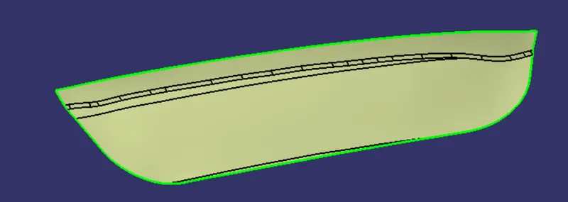
- First inpute a given class A surface to CATIA software.
- Aftering receiving the Class A surface check a connectivity of the surface on it.
- Use a join operation, boundary operation and dissemble.
STEP-2
TOOLING DIRECTION
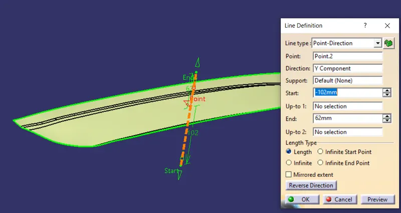
- Identify faces which can potentially creates a problem while manufacturing ,surface at angle along a desired tooling axis.
- Exract a plain surface and create a point on the surface for tooling axis direction.
- In this cases Y axis can be possible tooling axis direction.
STEP-3
DRAFT ANALYSIS FOR CLASS A SURFACE
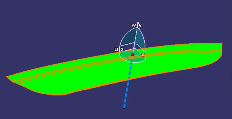
- Change a view mode customization to Material mode.
- Goto insert--->Analysis--->Feature Draft Analysis and move a compass to thetooling axis.
- click on the surface change a range value up to 2.9deg.
STEP-4
CLASS B SURFACE
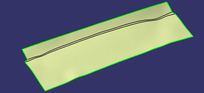
- Extract the relevant surface from the class A surface which excludes the fillets.
- Offset up to 2.5mm from the class A surface.
- Here it consists of 2 walls.
- Then extrapolate a surface of both walls and trime.
- Add a fillet for the edes.

STEP-5
CLASS C SURFACE
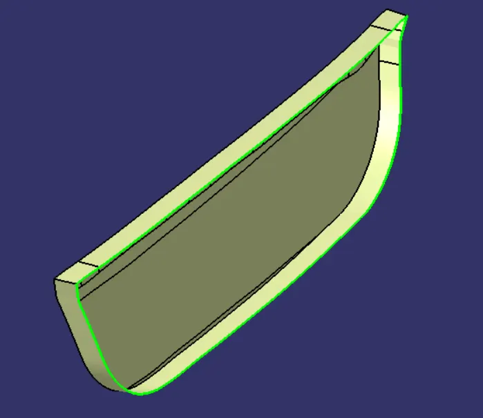
- Extract a edges of the Class A surface by using Multi-Extract operation then smooth a curve.
- Use a Sweep operation to extrude the boundary using "With draft direction" option selecting smooth curve as a guid curve and draft direction as a Tooling axis.
- Use a angle up to 3deg draft and select outward with appropratie length.
STEP-6
FINAL CLOSED SURFACE
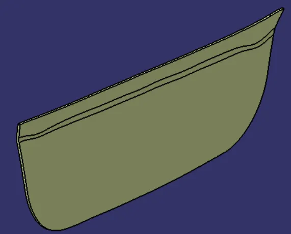
- Join all the Class Csurface witha class Asurface finally trim it with Class Bsurface.
- The finall trim should be one single surface entity without any gaps.
STEP-7
Create a closed body part from the final closed surface
- Swith to part design workbench and used closed surface operation to create a solid part from the final obtained surface.
- The part created is the required Applique designed from the class A surface.
STEP-8
Create Locators and Heat stack on the B surface
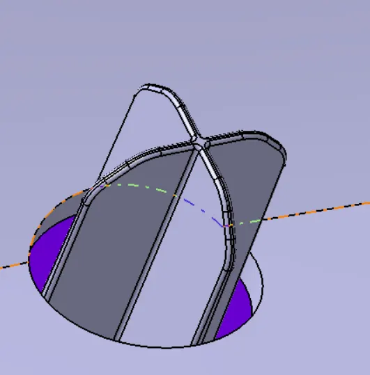
- Create a ZX Plane on the B surface.
- Create a sketch for a 4 way and 2 Way locators it should be fully Iso costraints.
- Extrude the sketch maintaining a thickness of 1.25mm as per rib design rules apply a Neytral fiber.
- To create a another 4 way locator use Translate option to the right side so that all the locators are placed equally far away.
- Make sure that height of the locators is maintained within the rib design rules.
Heat stack
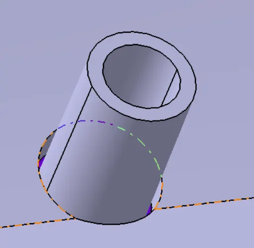
- Create a sketch of concentric circle for the Heat stakes.
- Maintain a wall thickness as per Rib design rules and extrude the Heat stacks at a level below the locators by atleat 5mm.
- Ensure that each Heat stack should maintains minimum 50mm as distance apart from easc other.
- Use a parallel curve option to create a points.
- Give a Draft angle for both inside and outside up to 0.5deg to wall of all locators and Heat stacks.
- Use a Union trime to keep the required faces with respect to th Applique body.
- Give a fillet and chamfers for locators.

STEP-9
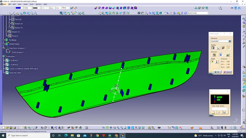
DRAFT ANALYSIS ON FINL COMPONENTS
- Draft is an angular tapering given at the design stage to every plastic components that has to be manufactured, it has to be given in the direction of the mold movements.
- The draft allows the parts to realese easily from the mold without creating friction between the surface of the components and core cavity plates.
- When a plastic components cools downs inside a mold, the natural tendency of it is to shrink and attach to the core or cavity plates.
Most application requires minimum draft angle of around 0.5 to 1deg, however 3deg draft angle are widely accepted for cost saving purposes. - 7Deg draft angle are given to textured surface like Instrument panels.
- Minimum draft angle are given for Ribs, Screw nosses due to critical nature.
- Whenever a draft angle is 0deg or negative draft it is difficult to manufacture, or required to redesign the class A surface.
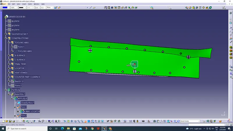
DIFFERENT VIEWS(ISOMETRIC,SIDE,TOP AND FRONT VIEW):
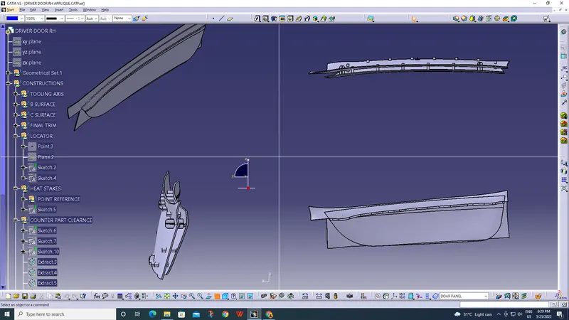
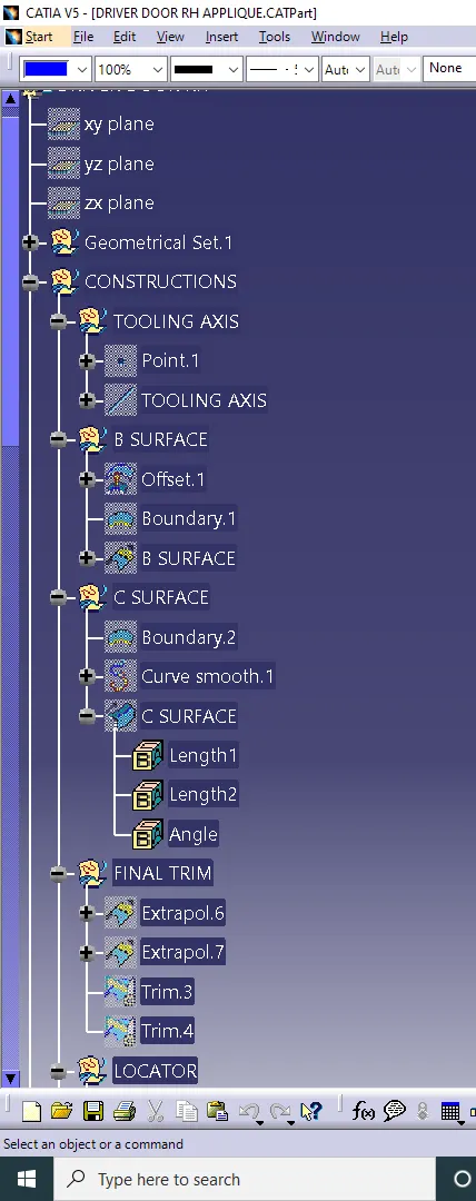
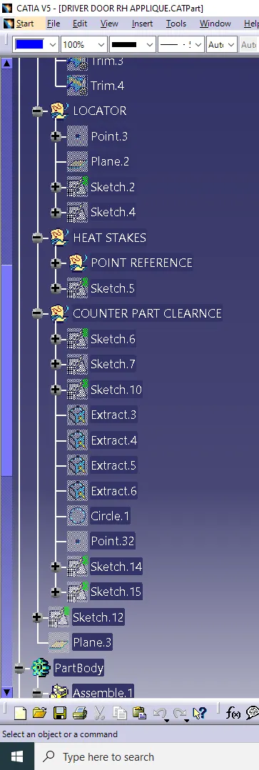
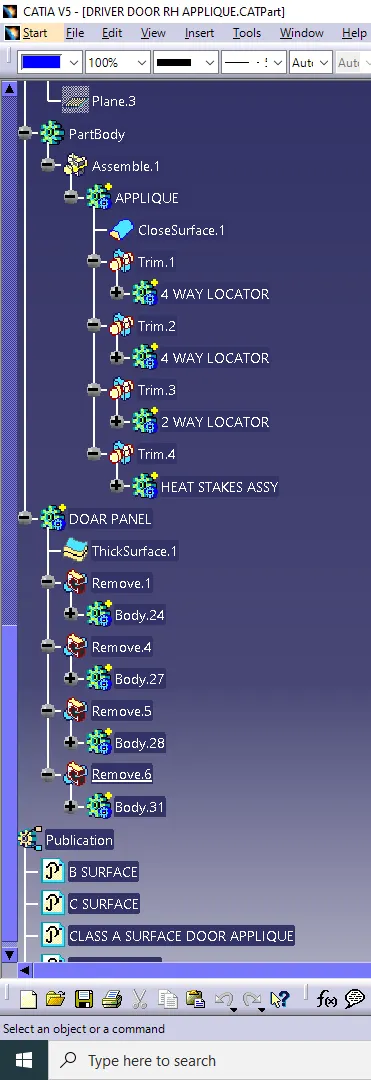
TREE STRUCTURE: